Hi!
I lurking on this forum for some time an trying to get needed info in posts. But, I'm confused regarding the selection of primary impedance of OPT in PP configuration. The answers can be found from " don't worry, take something in 5-6 K range" on one side and to precise selection of OPT for certain valve , scheme,...
I was trying different methods based on selecting OPT impedance from parameter charts and comparing my results with suggested values in schematics. Unluckily, I'm using pretty rare Russian valves (at least for amp application) 6P18P, for which I found only one usable schematic. There 5600 Ohms were suggested and 200V anode voltage.
Any suggestions, how to do the best selection/design?
THX
That's a good question, Kranj1.
In the Rudolf Moers book:
Fundamental Amplifier Techniques with Electron Tubes - ELEKTOR.fr | Électronique : Analogique Numérique Embarqué Microcontrôleurs Audio Test Mesure
He tested with a multitaped special output transformer many diferent loads for a tube.
He found that the 300B in single ended likes better a impedance of 5 times the internal anode impedance.
It seems that the teory tells another history.
That book is very big and I didn't read the push pull part!
If you wish to investigate further I think the book is a good investment, it mixes theory with pratice in a very scientific way.
Regards.
Walter.
One approach is to take the Max DC current spec from the "X" tube datasheet and compare it with the Max DC current spec of some well known audio tubes which do have a preferred OPT impedance spec'd for them. The higher the Max DC current spec is, the lower the OT primary impedance it will operate at (an inverse linear transform, --- this is assuming the same general B+ for all cases ---; high B+, or transmitting like, tubes should increase the Zprimary further by the B+ ratio used as well, versus the reference tube). You also need to check the tube watt dissipation on the selected Z loadline. This should get you in the initial ballpark at least. Generally, the higher the OT impedance used for a given tube, the less distortion, but also less power output. So you can make a tradeoff further from the initial estimate. Higher primary Z will also improve the damping ratio (lower output Z).
Using paralleled output tubes is an obvious extension of this method, just sum the max DC current specs. (or divide initial Zpri by the number of tubes in parallel)
Some max DC current specs:
Audio tubes
6V6/6AQ5 40 mA
6BQ5/EL84 65 mA
6CA7/EL34 150 mA
6L6GC/7581 110 mA
6550 190 mA
KT88 175 mA
7027 110 mA
KT120 250 mA
7868/7591A/6GM5 90 mA
Some common Sweep tubes:
6AV5/6BQ6 110 mA
6JN6/6JM6A/6GE5 175 mA
6HJ5 280 mA
6LB6 315 mA
6LQ6 350 mA
6LW6 400 mA
6KG6A/EL509 500 mA
Last edited:
The max DC current scheme above assumes both tube types are operating in the same class of operation, ie class A or class AB in order to make the Zpri scaling simple.
Some further refinements come from looking at the actual voltage swing the tube can perform (B+ minus the saturation V, instead of just the B+ ratios) and the plate curve knees.
Generally, low g2 voltages will allow more low end voltage swing, but less high end current swing (screen current picks up earlier). The load line and chosen Vg2 plate curve set in general are selected so the load line intersects just above the g1 = 0V plate curve knee. This gives max power output for the selected Zpri while protecting the screen grid from overcurrent during overdrive situations (very important). Ie, once you select a Zpri, the screen grid voltage must be determined for safe operation. This could also be done with an O'scope with a current probe and a variable screen V supply, or watch the current meter pickup on the screen supply at max signal (Vg1 going just above 0V with respect to the cathode).
Then one can also rough calc. the distortion on the chosen load line (have to combine both P-P tube currents and take into account the tube biasing as well). This is really getting into the nitty-gritty of interpreting the tube curves then. You could also try a simulator if you have a good tube model, but few models take screen current into account accurately.
Last edited:
He tested with a multitaped special output transformer many diferent loads for a tube.
This is how I do it, since many tubes don't actually work the way the data sheet states, especially sweep tubes that were uprated several times over their life without changing the data sheet. Even the old ones were never intended for audio amps, so no useful data exists.
You don't need a special multi tapped transformer, just an ordinary OPT rated for enough power, and a tapped load resistor. OK, not actually a tapped resistor, just a bunch of 1 ohm resistors in series, and maybe a 4 ohm resistor.
An OPT acts like a lever, it has a fixed ratio over a reasonable range. This means that you can change the secondary load and have the ratio reflected on the primary. So with a 6600 ohm OPT and the collection of resistors I can emulate a range of OPT's. The transformer has a 6600 ohm primary with an 8 ohm load on the 8 ohm tap (normal load). So we divide the 6600 ohms by 8 to find the ratio of 825 primary ohms for each secondary ohm. this allows 3300 ohms with a 4 ohm load on the 8 ohm tap, 4125 ohms with 5 ohms and so forth. A decent OPT that is a bit oversized for the application can usually be used over a 2 to 1 range so my 6600 OPT works from 3300 to 13200 ohms.
This way you can find out what impedance the tubes really like.
Most P-P amps are a trade off between power, distortion, and maximum tube current. With a big sweep tube the maximum tube current determines the maximum power output. Keep lowering the load impedance until the maximum current is reached, or the tube starts to glow red. The glow will not happen on music since you are not cranking full power sine waves cotinuously. Most class AB P-P amps use some feedback to improve the distortion and damping factor. If there is no feedback, the distortion or damping factor determines maximum power output.
An SE amp will always run in class A often without feedback. Here the distortion VS power trade off determines the optimum load.
Hopefully someone with experience with this tube or Russian tubes in general can make some suggestions.
Having no experience with this tube, take my following comments with liberal doubts.
First of all, the 11K gm should be close enough to a 6BQ5 that you can use P-P 6BQ5 schematics for the prior gain stages. Just the output stage needs optimising.
These rounded knee tubes were generally intended for single ended class A operation in a TV set, either Vertical Sweep or Audio output. The rounded knees were used to help remove 2nd harmonic distortion in SE mode. For P-P mode, this rounding will cause extra compression and odd harmonic distortion at high signal levels. To minimise this, if you can afford to lose some Watts, go for a higher Z OT (and use the Max B+ the tube is rated for) like maybe a 6K Ohm P-P OT (even as high as an 8K P-P, but with even lower power out). This will help keep the operating region away from the curved knees better. Better yet, try several surplus OT impedances with variable B+ and g2 supplies and listen to the results, see what you are happy with.
Edit:
Just saw George's comments above, a good way to test with a single available OT. If you don't have some means to test for distortion like a sound card FFT, then maybe you can put a headphone across a resistive divider from the load resistor to listen to the sound.
Last edited:
I have some of these and waiting for good schema's and OPT's as well...
Here is the good link for Russian valves in amps. It's in Russian language only, but I do speak a bit Russian (have learned for my business needs). In case of need I can help on translation.
I also have some PDF documents about many different Russian valves and schematics, which can be found on the Net.
Thanks guys for your help. I'll play a bit with your suggestions to further confirm that 5600 is acceptable. Must hurry up to finish this amp for my son (as a gift for finishing secondary school).
Regards!
Story goes on..
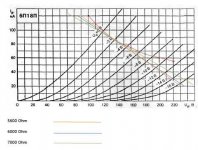
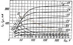
In attachment you can see two graphs; one in triode and second in pentode connection. I placed 12W limitation curve and three "working" lines for 5600, 6000 and 7000 Ohms. In triode mode I get from 1,2W to 3,5W and in pentode from 5W to 10W. Don't know what would be in UL mode.
The funny thing is that my calculated result (approx. 7W) is not equal to in schematic suggested power (9W).
What I'm doing wrong?
Attachments
The link is good...i've been here...and actually i've already build the 6R2P amp from sergey komarov....i have posted it somewhere in this forum...
i just finished it tweaking yesterday and found the problem....now i'm satisfied with the final result and sound was very good especially the vocal and highs...
i dont mean to thread jack, but i have a question im sure one of you can awncer,
i have 12 pl500 sweep tubes that i was going to use to build two monoblocks with, if i configure 6 of them in push pull parallel (per channel),using the prescribed voltages on the spec sheet, what sort of primary resistance and wattage opt do i need to look for?
here is the pdf...
http://www.r-type.org/pdfs/pl500.pdf
thanks in advance
- Status
- This old topic is closed. If you want to reopen this topic, contact a moderator using the "Report Post" button.
- Home
- Amplifiers
- Tubes / Valves
- PP OPT design