Hi, folks,
I have stability problems with PP UL amp, 2xKT88, 3.9K transformer, 460V B+.
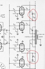
There is a common trick, described in several sources, connecting RC snubber between anode and grid #2 of the output tube (see reference schematic attached). This trick worked for me, BUT, now I have considerable high frequency roll-off.
The original author of the schematic mentioned above used 5 pairs of KT88, and 1K + 0.001 uF snubber. Looks like he had 1K transformer, and upper frequency limit stated 25 KHz.
Taking into account difference in transformer impedance, I used 4.7k resistor + caps in range of 47 pF - 1000 pF. With caps 500 - 1000 pF high frequency roll off is down to 13.6V (20 KHz) from 20V (2KHz), and with 47 pF down to 15.6V.
Anyone can suggest how to select RC values, maintaining stability, yet without roll off at high frequencies?
Thanks in advance for any suggestion(s).
I have stability problems with PP UL amp, 2xKT88, 3.9K transformer, 460V B+.
There is a common trick, described in several sources, connecting RC snubber between anode and grid #2 of the output tube (see reference schematic attached). This trick worked for me, BUT, now I have considerable high frequency roll-off.
The original author of the schematic mentioned above used 5 pairs of KT88, and 1K + 0.001 uF snubber. Looks like he had 1K transformer, and upper frequency limit stated 25 KHz.
Taking into account difference in transformer impedance, I used 4.7k resistor + caps in range of 47 pF - 1000 pF. With caps 500 - 1000 pF high frequency roll off is down to 13.6V (20 KHz) from 20V (2KHz), and with 47 pF down to 15.6V.
Anyone can suggest how to select RC values, maintaining stability, yet without roll off at high frequencies?
Thanks in advance for any suggestion(s).
Attachments
I don't think that the output transformer snubbers are a good place to put phase lag. Besides power handling issues it's sensitive to output loading. Not knowing anything else about your amplifier, I can only suggest sticking to the conventional high frequency rolloff further upstream and use the output transformer RC's as snubbers to damp parasitic reactances in the transformer.
That's an old fashioned way to do things, but probably easier to get going well.
All good fortune,
Chris
That's an old fashioned way to do things, but probably easier to get going well.
All good fortune,
Chris
If you want to get into some theory and maths look here:
Damping of ringing in audio transformers
You may need to navigate around VoltSeconds site a bit to find what you need.
Else - my short cut.
Each side of the push pull is 60% A to G2, 40% G2 to Centre Tap.
So turns anode to anode is 0.3 + 0.2 + 0.2 + 0.3
So you need to shunt 0.3 of total turns. That will look like 0.3 x 0.3 = 0.09 of total impedance.
0.09 of Raa=3900 gives 351 Ohms.
For a Zobel Network you use a resistor value of 1.4 to 2 x the impedance you are shunting. So 491 Ohms to 702 Ohms.
Use say 560 Ohms.
Then increase the cap until it is stable.
Quick calc for a start value.
Choose say 60kHz as the roll off.
Multiply 60,000 by 2 pi, hit the 1 over button and then divide by 560
That gives just about exactly 4n7.
I'd probably try 2n2 to see if that was enough but go higher if required.
Cheers,
Ian
Great stuff! If you make it that easy might be interesting to try splitting Zobels between primary and secondary. Just enough on the primary to make open loop scope square waves look pretty and another on the secondary to tame whatever potential stability issues.
Thanks,
Chris
Thanks,
Chris
If you want to get into some theory and maths look here:
Damping of ringing in audio transformers
You may need to navigate around VoltSeconds site a bit to find what you need.
Thanks for everyone who replied !
Dumping ringing is not something I'm looking for. Square wave response at 2 KHz is near perfect at several V.
Amps works fine when load is connected to 8 ohm tap, but unstable if to 4 ohm tap.
With another output transformer it oscillates after certain power level reached no matter of load connection (I have 4 different transformers).
Snubbers between anode and grid 2 terminated instability completely, but introduced high frequency roll off. Quite strange, since in another amp I mentioned there was no such side effect.
Any idea how to avoid HF roll off with anode-grid2 snubbers?
. . .
Any idea how to avoid HF roll off with anode-grid2 snubbers?
Go away from UL and feed screens with a clean and stable supply
")
Yves.
I don't think that the output transformer snubbers are a good place to put phase lag. Besides power handling issues it's sensitive to output loading.
Are you sure? Oscillation is normally caused by leakage inductance and capacitance, which are more-or-less independent of loading and unique to the transformer.
Snubbers between anode and grid 2 terminated instability completely, but introduced high frequency roll off.
At what frequency does it start rolling off?
Last edited:
Can we just be clear whether we are dealing with output stage parasitic oscillation or global loop instability? Adding snubbers to the OPT could affect both.
Moving the load from 8ohm to 4ohm tap will reduce the loading on the OPT and hence reduce damping on any resonance.
I can check it when return back.
Quite possible stability affected by the very long interconnection wires, I have separate power supply sitting on another side of the table.
At what frequency does it start rolling off?
With snubbers installed, roll off starts at 10 - 12 KHz, depending upon value of C (even with 45 pF).
Without snubbers, there is no roll off at audio frequency range.
Book published by G.E.C. "An approach to audio frequency amplifier design" recommends anode-grid2 snubbers for UL 1000 - 2000 pF + 470 - 1500 Ohm.
Last edited:
Circuit diagram SVP ?
Most are correct; high gm tubes like the 88 do need an anode to g2 snubber regardless of transformer and unsuprisingly wide values can be effective and just relevant to the output stage. There is far more to the this; I would start by also examining the first stage anode stage if that zobel is fitted because that determine the Bode plot loop gain at the upper end that no response peak exists after gloal NFB is connected.
richy
Dumping ringing is not something I'm looking for. Square wave response at 2 KHz is near perfect at several V.
Amps works fine when load is connected to 8 ohm tap, but unstable if to 4 ohm tap.
With another output transformer it oscillates after certain power level reached no matter of load connection (I have 4 different transformers).
Snubbers between anode and grid 2 terminated instability completely, but introduced high frequency roll off. Quite strange, since in another amp I mentioned there was no such side effect.
Any idea how to avoid HF roll off with anode-grid2 snubbers?
If you're seeing a significant rolloff with only 45pF in the snubbers, something is *not* as we think it is.
As DF96 has tried to emphasize, we need to distinguish between measures designed to damp output stage parasitics and measures designed for loop stability. The former are important even in an amp without a global loop.
And as I have tried to emphasize, the output transformer primary snubbers are not a good place to put measures for global loop stability. (However, a Zobel across the secondary is both easy and uniformly positive WRT global stability - maybe 10 or 15 Ohms and 0.1uF.)
All good fortune,
Chris
You do have some local supply rail decoupling on the amp side of the table, don't you? Otherwise the long supply wires could act as Lecher lines.LinuksGuru said:Quite possible stability affected by the very long interconnection wires, I have separate power supply sitting on another side of the table.
45pF could have an effect - remember we are talking about 10's or 100's of H. You don't need much capacitance to resonate within the audio band, which is partly why decent OPTs are expensive.
Last edited:
Hi, folks !
Thanks a LOT to all who replied with helpful ideas, tips and suggestions!
Schematic is slightly modified Williamson (available in a bunch of sources), switchable between penthode, UL, CFB, UL+CFB, and triode mode, adopted to KT88 / KT120 / 6550, fixed BIAS and 460-490V B+.
I tested it with 4 different custom built 60W / 3.3K - 3.9K transformers.
Since it is draft / test assembly, everything laying across the table, wires are long as road to Siberia (B+/GND - 80 cm, filament - 60 cm, transformer leads - 28 cm, input signal wire - 1 m).
DC supply rails are decoupled with electrolytes and 1000 pF ceramic caps.
Filament common for all 4 tubes, false center tap (made with 2 x 100 Ohm resistors) lifted to 40V with resistor divider from B+.
One transformer worked fine out of the box, another caused oscillation of UL even with GNFB disconnected, third only at high signal level (with GNFB on).
Williamson is very well known to be very picky when it comes to output transformers. However, I managed to get ALL of them to work, with up to 60W in UL mode. Since leakage inductance is in range 8 - 18 mH (depending upon particular transformer), it appears stray capacitance (all iron is quite big !) played major role in stability issues.
The cause of high-frequency roll off (described in my 1st post) was the conjunction of high-frequency RC filter (10K + 500pF) in pre-driver which was installed to cut off everything above audio band, and anode-grid#2 snubbers (seprately they don't have such side effect). Removing RC filter from pre-driver solved this problem.
Anode / grid#2 snubbers were suggested in a book published by G.E.C. "An approach to audio frequency amplifier design". In my case they are 4.7K + 1000 pF.
I didn't tried Zobel at secondary, it was not necessary at this time, additionally, it could "mask" high frequency oscillation if its level is small (once, with another amp, I had 8mV - 20mV at 8 Ohm output terminals).
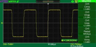
THD/IMD analysis was not made yet at this moment, I just put away soldering iron, but picture looks promising. There is no stability issues or oscillation with any trafo I have (only slight tremble of picture on oscilloscope screen with output signal at very low level, e.g. 100mV), even at heavy overload / clipping.
Just look at present 2 KHz square wave with worst transformer, which at the beginning didn't worked at all (oscillated in UL mode with GFNB off).
Thanks a LOT to all who replied with helpful ideas, tips and suggestions!
Schematic is slightly modified Williamson (available in a bunch of sources), switchable between penthode, UL, CFB, UL+CFB, and triode mode, adopted to KT88 / KT120 / 6550, fixed BIAS and 460-490V B+.
I tested it with 4 different custom built 60W / 3.3K - 3.9K transformers.
Since it is draft / test assembly, everything laying across the table, wires are long as road to Siberia (B+/GND - 80 cm, filament - 60 cm, transformer leads - 28 cm, input signal wire - 1 m).
DC supply rails are decoupled with electrolytes and 1000 pF ceramic caps.
Filament common for all 4 tubes, false center tap (made with 2 x 100 Ohm resistors) lifted to 40V with resistor divider from B+.
One transformer worked fine out of the box, another caused oscillation of UL even with GNFB disconnected, third only at high signal level (with GNFB on).
Williamson is very well known to be very picky when it comes to output transformers. However, I managed to get ALL of them to work, with up to 60W in UL mode. Since leakage inductance is in range 8 - 18 mH (depending upon particular transformer), it appears stray capacitance (all iron is quite big !) played major role in stability issues.
The cause of high-frequency roll off (described in my 1st post) was the conjunction of high-frequency RC filter (10K + 500pF) in pre-driver which was installed to cut off everything above audio band, and anode-grid#2 snubbers (seprately they don't have such side effect). Removing RC filter from pre-driver solved this problem.
Anode / grid#2 snubbers were suggested in a book published by G.E.C. "An approach to audio frequency amplifier design". In my case they are 4.7K + 1000 pF.
I didn't tried Zobel at secondary, it was not necessary at this time, additionally, it could "mask" high frequency oscillation if its level is small (once, with another amp, I had 8mV - 20mV at 8 Ohm output terminals).
THD/IMD analysis was not made yet at this moment, I just put away soldering iron, but picture looks promising. There is no stability issues or oscillation with any trafo I have (only slight tremble of picture on oscilloscope screen with output signal at very low level, e.g. 100mV), even at heavy overload / clipping.
Just look at present 2 KHz square wave with worst transformer, which at the beginning didn't worked at all (oscillated in UL mode with GFNB off).
Attachments
- Status
- This old topic is closed. If you want to reopen this topic, contact a moderator using the "Report Post" button.
- Home
- Amplifiers
- Tubes / Valves
- Q: UL PP Instability - Anode Grid2 Snubber