I have read all available threads (also the "suggested" threads when writing this post) but to no avail.
I woul oike to use both the supertex dn2540 and IXYS 10m45s part as single device CCS
To do that I must select an appropriate Rset value (2.2k gate stoppers on each device).
The application requires 3mA and 5mA (both the supertex device and IXYS device will have to provide either one or the other). With a 2.2k gate stopper I thought of adding a 5k multiturn linear trimmer on the IXYS devices but I am not sure the same value would work for the supertex part.
The datasheet for the IXYS device does provide a graph with the Rset to current relationship however there the supertex datasheet does not.
Could someone please address the following questions?")
1. Is a 5k multiturn pot a good choice to precisely achieve 3mA or 5mA from either device as a plate CCS? Is a larger value (ie 10k) better for such small currents?
2. What exactly is the correct value for each device (single IXYS and single SUPERTEX) to achieve 3mA and 5mA?
Thank you for any reply
Cheers
I woul oike to use both the supertex dn2540 and IXYS 10m45s part as single device CCS
To do that I must select an appropriate Rset value (2.2k gate stoppers on each device).
The application requires 3mA and 5mA (both the supertex device and IXYS device will have to provide either one or the other). With a 2.2k gate stopper I thought of adding a 5k multiturn linear trimmer on the IXYS devices but I am not sure the same value would work for the supertex part.
The datasheet for the IXYS device does provide a graph with the Rset to current relationship however there the supertex datasheet does not.
Could someone please address the following questions?
1. Is a 5k multiturn pot a good choice to precisely achieve 3mA or 5mA from either device as a plate CCS? Is a larger value (ie 10k) better for such small currents?
2. What exactly is the correct value for each device (single IXYS and single SUPERTEX) to achieve 3mA and 5mA?
Thank you for any reply
Cheers
I have read all available threads (also the "suggested" threads when writing this post) but to no avail.
I woul oike to use both the supertex dn2540 and IXYS 10m45s part as single device CCS
To do that I must select an appropriate Rset value (2.2k gate stoppers on each device).
The application requires 3mA and 5mA (both the supertex device and IXYS device will have to provide either one or the other). With a 2.2k gate stopper I thought of adding a 5k multiturn linear trimmer on the IXYS devices but I am not sure the same value would work for the supertex part.
The datasheet for the IXYS device does provide a graph with the Rset to current relationship however there the supertex datasheet does not.
Could someone please address the following questions?
1. Is a 5k multiturn pot a good choice to precisely achieve 3mA or 5mA from either device as a plate CCS? Is a larger value (ie 10k) better for such small currents?
2. What exactly is the correct value for each device (single IXYS and single SUPERTEX) to achieve 3mA and 5mA?
Thank you for any reply
Cheers
All will be less than 1K. A smaller value pot is better to make the adjustment less sensitive. I'd use a 1K pot.
I checked again the IXYS 10m45s datasheet. Actually according to the datasheet 1k would seem to be exactly the value needed for 3mA.
However the dn2540 part usually requires a higher value no?
I'm going by the datasheet and memory that the DN2540 cuts off below about 2.2 volts The official max Vgs cutoff is -3.5 volts which would require 3.5 mA through the 1K resistor. So I think you're pretty safe with 1K and the DN2540.
With the 10M45 I recall always needing a smaller resistance than the datasheet chart shows. Closer to the 10M90 spec actually...
Those devices don't work well below 10ma. For values that low, I'd use a cascoded LM134/LM334 and 10m45s or dn2540. I use Walt Jung's circuit that he used for his article on constant current sources for the LM317 and 10M45s cascode, except the physical pinout of the LM134 is reversed from the pins of the LM317. The LM134/334 datasheet has values for the Rset that are more accurate and consistent than the depletion mode MOSFETS.
very nice. I remembered the combo from the article...just a few questions.
1) Could you please define bad? Noise rejection/reliability...?
2) why replace lm317 with lm334? The schematic shown in the article seems to be "ideal" (words of the author) Is the load too low even for lm317+dn2540?
Thanks!
1) Could you please define bad? Noise rejection/reliability...?
2) why replace lm317 with lm334? The schematic shown in the article seems to be "ideal" (words of the author) Is the load too low even for lm317+dn2540?
Thanks!
The problem with the MOSFET alone or with the LM317 is that at low currents (less than 5-10ma) the dropout voltage becomes too low and they become either unstable or unable to keep regulation. The LM334 has a maximum of about 10ma while the LM317 has a minimum of around 5 ma. Below 5ma I use the LM334 with great success (see: http://www.diyaudio.com/forums/tubes-valves/211352-new-amp-13de7-se-hybrid.html). I use the stabilization network as cheap insurance - it costs little and can't hurt.
with a lm334 a good value trimpot would apparently be 100ohm. Correct?
Also in the schematic (by Jung) there is the R/C stabilization network but also a cap from B+ to ground. Could someone elaborate on that?
Thanks!
P.s. I read the thread you opened. Nice design. I for one like the mosfet in the output!
Also in the schematic (by Jung) there is the R/C stabilization network but also a cap from B+ to ground. Could someone elaborate on that?
Thanks!
P.s. I read the thread you opened. Nice design. I for one like the mosfet in the output!
is this schematic correct?
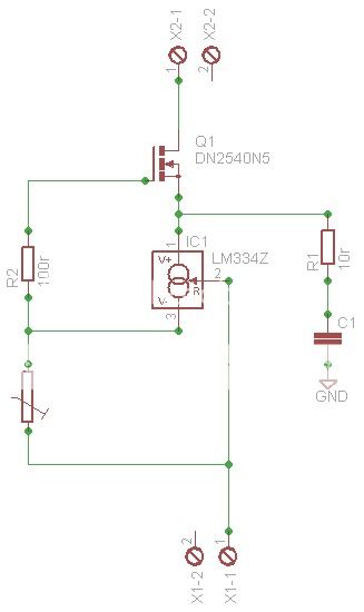
For 3mA and 5mA plate current
Hi Alex,
The LM317 and LM334 are not just different pinouts. They're fundamentally different devices. The LM317 is a 3 terminal voltage regulator, while the LM334 is an adjustable current source. It's worth studying the datasheets to understand how they would work in Walt Jung's circuits.
The LM317 can also be used as a current source by placing the sensing resistor in series with the output and connecting the adjust terminal to the output end of the resistor.
The LM317 has a minimum current of about 1.5 mA (+ 100uA adj pin current) when used at low Vin-Vout as you are in the bottom device of a cascode. The dropout voltage is only a problem when it gets too *HIGH* at higher currents. Basically the issue with the 317 is that the Vgs of the top device must be greater than the dropout voltage of the LM317. At your op point the dropout voltage should be about 1.2V, which is fine for either 10M45 or DN2540. See Walt Jung's article for a full explanation of this issue.
The LM317 adjust pin operates on a negative voltage and sources a small curent into the device. The LM334 R pin operates with positive voltage on a small current supplied by the device.
Your proposed circuit will work for the LM317 but not for the LM334. For the LM334 you should look at the datasheet examples and see how the R pin is used. The gate of the MOSFET (stopper R) and the output would both connect to the V- pin of the LM334 and the Rset connects between V- and R pins.
BTW, the DN2540 should work just fine by itself if your circuit can tolerate a little temperature drift. That's really the only issue IME.
Thanks michael. A very informative and clear answer! i will study the datasheets thoroughly. I am sorry for having wasted your time with my schematic but hopefully the thread will remain to educate others on how to use these devices.
Inviato dal mio GT-I9001 con Tapatalk 2
Inviato dal mio GT-I9001 con Tapatalk 2
Like me for example. Thanks for the clearifications. One question tho. Fenris states thathopefully the thread will remain to educate others on how to use these devices.
and Michael thatThe problem with the MOSFET alone or with the LM317 is that at low currents (less than 5-10ma) the dropout voltage becomes too low and they become either unstable or unable to keep regulation.
If wanting to regulate current on an ECC83 for example, under 5 mA, is a DN2540 ok there alone or does it need a partner?the DN2540 should work just fine by itself if your circuit can tolerate a little temperature drift
Staffan
I don't consider it a waste of time at all. This is important learning for everyone.
Dropout voltage of a regulator is the minimum input-output voltage required to maintain it's output regulation. Below the minimum dropout voltage the output of the regulator can become unstable; usually the output will start to follow the input voltage.
The dropout voltage usually decreases as the load current decreases due to finite gm devices and other circuit operational factors.
In the self-biased cascode, the lower device derives it's operating voltage from the control voltage of the upper device. The control voltage of the DN2540 at 5 mA is over 2 volts. That gives the lower device > 2 volts dropout voltage to work with.
The LM317 has a datasheet spec of 3.5 volts, but this is over the entire working range of the device, which can pass over 1 amp. There is also a curve of dropout voltage vs. current and temperature that shows in the range of 1-10 mA it only needs about 1.5 volts minimum.
MOSFETS do not have a dropout voltage. At lower voltages the capacitance increases until at some point the desired response of the circuit can be compromised.
Here is the 2 part current regulator article that is being referenced:
http://waltjung.org/PDFs/Sources_101_P1.pdf
http://waltjung.org/PDFs/Sources_101_P2.pdf
And this is really 101, just an introduction into the process of designing with constant current circuits. It should be treated as a nice set of design examples but not complete. For example, the noise/stability tradeoff will be very different for a plate load for the first stage of a phono preamp vs. a generating a bias voltage across a large value grid resistor.
I can assure you that a DN2540 works quite well down below 1 mA and I can't imagine what the problem would be other than a little temperature drift, which you will need to evaluate for suitability in your circuit. If you need more stability, the LM317 cascode seems like a good candidate. A cascode of DN2540 is also a good circuit which will be much more temperature stable than a single device.
The LM334 has a temperature slope of 1%/3 degrees C and can be used as a thermometer ;-) it can be made temp stable with an extra component or 2...
Last edited:
I have wondered why people don't use a JFET as the bottom device. I'm in the process of designing a CCS for large swings (200Vrms) for a stage running at 10mA and want to keep the load line as flat as possible. I was considering 10M90S on top and J109 as the bottom device. I've never used JFETs before so don't know if there is some reason not to do this in a tube load. From what I can tell the DN2540 would work well as a bottom device @ 10mA with 3V or so across it too (nice flat curves in that region).
JFETs tend not to be consistent in Idss from unit to unit. I've got a bunch of 2SK170s that vary from 3ma to over 10ma, and all are from the same batch. It takes a minute to put each into a test rig, wait for them to temperature stabilize, and then write down the value. Trimming the circuit for each device can be annoying for the DIYer and downright unproductive for a manufacturer.
The LM334 may not be a voltage regulator like the LM317, but in the circuit they both function as current regulators. The temperature drift is pretty small, only a couple of percent over the normal operating range.
I use Walt Jung's circuits because the 317 and 334 have very predictable and calculateable (is that a word?) Rset values from the datasheet. The 10M45s and DN2540 are too inconsistent to use datasheet values and I don't want to have to measure each one individually. And I know the LM334 works in the circuit because I've used it and it was right on spec.
Very informative thread, thanks! The LM3XX have like 3,5 dropout as been said in spec for max current but it is known that for good regulation they need substantually more, over 5 V is recommendable. I guess that has to do with counting the ripple in. But I guess that is nothing to be taken in concideration as lower device in a self-biased cascode since the upper already have regulated/smoothed that out?
- Status
- This old topic is closed. If you want to reopen this topic, contact a moderator using the "Report Post" button.
- Home
- Amplifiers
- Tubes / Valves
- Supertex dn2540 CCS Rset trimmer value