New schematics
Hi,
Now I'm working tube pre-amp with ECC88 under this new corrected schematics: http://imageshack.us/content_round....mlaKrnaWS09zN1N7S2dPd2MfZ6dve19Opytax19iR2-HN
If the seeds are not something you like you can just tell that corrected?!
thank you!
Hi,
Now I'm working tube pre-amp with ECC88 under this new corrected schematics: http://imageshack.us/content_round....mlaKrnaWS09zN1N7S2dPd2MfZ6dve19Opytax19iR2-HN
If the seeds are not something you like you can just tell that corrected?!
thank you!
Last edited:
Wondering which pre-amp?
thank you!

After finished my simple 12AX7 tube preamp, I decided to try other medium mu tubes, including the 12AU7 and also this 6922.
The design is almost the same as the 12AX7 preamp, it is a single gain stage triode tube with cathode follower. However there is an important difference, a 1k "stopper" resistor is added at each grid input. This 1k resistor is required to avoid parasitic oscillation. Without it, the 6922 would oscillate easily.
Please note that you should NOT use 6DJ8 in this design, as the heater-cathode maximum voltage limitation is different with 6922. Besides 6922, the E88CC or E188CC tubes can be used.
Schematics :

Gain stage loadline :

Cathode follower loadline :

When design the loadline for the cathode follower, the 6922's maximum cathode to heater voltage limit of 150V has to be taken into consideration. The cathode voltage is chosen at 90V so that the 150V limit is not exceeded. If the cathode voltage exceed 150V, the heater is needed to be elevated. However, if the heater is elevated then its ground is not grounded, the heater supply wire can pick up noise or EMI more easily. My measurement showed that when the heater is elevated the amp's noise floor is increased by more than 10dB. So I would avoid heater elevation if possible.
For 90V cathode that means the tube has to drop 160V. I also want the tube to have a high output current at 9mA, so the operation point (the red dot) is chosen at 9mA and 160V. The load line can then be drawn by connecting the red dot and B+ at the voltage axis.
I am not going into the details that how the resistor values are calculated, please reference to my 12AX7 preamp page if you want more information.
The gain for this amp can be calculated by this formula :
Gain = (Tube Gain x Plate load resistor)/(plate load resistor + plate resistance + ((tube gain +1) * cathode resistor)).
With 6922, the plate resistance = 3k, tube gain = 33. Using these value in the above formula, the calculated gain is 22.
The output impedance of the 1st gain stage is equal to the plate load resistor paralleled with the plate resistance, so in my case it is about 2.7k, which is a bit high. So a cathode follower is needed to reduce the output impedance. With the cathode follower, the output impedance would roughly equal to 1/(tube's transconductance).
For 6922, its transconductance is about 12000 micromhos. So the cathode follower's output impedance would be at about 85 ohms, which is a good low figure.
It is very important that the regulated power supply can provide a clean B+ and heater voltage supply. For this design, any ripple in the B+ line will appear on the output signal. Noise or ripple in the heater supply will also be coupled to the output.

With the use of the copper component stands, I can change components easily. This is especially useful for trying out different loadlines.

DACT switched volume control, it has very smooth switching action

DACT 4 poles 5 positions input selector. Both signal and ground are switched.

The 6922/E88CC has low distortion, high output current, and has high transconductance which make a cathode follower with low output impedance of 85 ohms. All these properties make the 6922 a good choice as a preamp tube.

In fact, among the 3 tube preamps I created, this 6922 preamp sounds the best, it has the most resolution details and having excellent dynamics. I like it so much that I searched for the best 6922/E88CC tubes to use in it.
Page 1 of 2
Hi ARIYAHOOR!
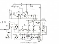
This preamplifier is known, but to give schematics a power supply!
Tnanks
Insert the schematics for power supply!
Your work is stunning.
I have not seen these copper component stands before. Nor can I find them under that name. Does anyone know if they go by a different name?
When design the loadline for the cathode follower, the 6922's maximum cathode to heater voltage limit of 150V has to be taken into consideration. The cathode voltage is chosen at 90V so that the 150V limit is not exceeded. If the cathode voltage exceed 150V, the heater is needed to be elevated. However, if the heater is elevated then its ground is not grounded, the heater supply wire can pick up noise or EMI more easily. My measurement showed that when the heater is elevated the amp's noise floor is increased by more than 10dB. So I would avoid heater elevation if possible.
Proper decoupling of the elevated heater voltage avoids this problem.
With the cathode follower, the output impedance would roughly equal to 1/(tube's transconductance). For 6922, its transconductance is about 12000 micromhos. So the cathode follower's output impedance would be at about 85 ohms, which is a good low figure.
Note this is the small signal output impedance.
It is very important that the regulated power supply can provide a clean B+ and heater voltage supply. For this design, any ripple in the B+ line will appear on the output signal. Noise or ripple in the heater supply will also be coupled to the output.
Susceptibility to HT noise can be avoided by proper decoupling of the first stage which has a very poor power supply rejection ratio (PSRR). The cathode follower has a PSRR of about 1/mu or about 30dB.
Cheers
Ian
I have not seen these copper component stands before. Nor can I find them under that name. Does anyone know if they go by a different name?
Yes, they are also called turrets.
Thanks, I like the forked ones, but their tubes are expensive!Yes, they are also called turrets.
Touching (again?) on the poor PSRR of triode stages, particularly the high-current ones, I might mention that I have used a two-stage transistor/fet follower in series with the power line with a double RC integrator in each base/gate circuit (no constant voltage regulation as such).
This way one can get rail ripple down to 200 - 500µV on a 250V supply, which did not come through on the signal output in the final result. It also yields a quite slow turn-on of h.t. where such is deemed important.
This way one can get rail ripple down to 200 - 500µV on a 250V supply, which did not come through on the signal output in the final result. It also yields a quite slow turn-on of h.t. where such is deemed important.
Touching (again?) on the poor PSRR of triode stages, particularly the high-current ones, I might mention that I have used a two-stage transistor/fet follower in series with the power line with a double RC integrator in each base/gate circuit (no constant voltage regulation as such).
This way one can get rail ripple down to 200 - 500µV on a 250V supply, which did not come through on the signal output in the final result. It also yields a quite slow turn-on of h.t. where such is deemed important.
Not enough is written about low noise HT supplies for preamps unless it is endless discussion of the minutae of semiconductor regulators. Back in the late 1940s Scroggie wrote an excellent article on the benefits of cascaded RC filters which was picked up by Morgan Jones in his book. Using Scroggie's methods it is quite straightforward to design a preamp power supply with ripple/noise around a few microvolts.
Cheers
Ian
With 1 Vrms input THD is more than 1.2 %.
So it is not a high-end pre amp.
But after some modifications it would be.
Hi artosalo!
At the output of the second harmonic 1Vrms less than 0.5% (2 harmonic <0.5% and 3 harmonic<0.03).
It is true tube/valve preamplifier!!


If you have any suggestions about some changes to the schematic go ahead!
Best regards!

Last edited:
At the output of the second harmonic 1Vrms less than 0.6% (2 harmonic <0.6% and 3 harmonic<0.03).
Do you mean that this is the THD with 1 Vrms output voltage or with 1 Vrms input voltage ?
Anyhow, even 0.6 % of 2nd harmonic is not a feature of high end pre amp.
Do you mean that this is the THD with 1 Vrms output voltage or with 1 Vrms input voltage ?
Anyhow, even 0.6 % of 2nd harmonic is not a feature of high end pre amp.
1Vrms output voltage,...
People can not hear distortion <0.2%
Cheers!
Last edited:
If 1 Vrms is sufficient output level, why this amplifier is having the gain of 20 (=26 dB).
1 Vrms is achieved with 50 mV input voltage.
I think that typical input voltage is between 0.5...2 Vrms and if 1 Vrms is OK as the output level, should the gain of the amplifier be something 6 dB or so ?
1 Vrms is achieved with 50 mV input voltage.
I think that typical input voltage is between 0.5...2 Vrms and if 1 Vrms is OK as the output level, should the gain of the amplifier be something 6 dB or so ?
If 1 Vrms is sufficient output level, why this amplifier is having the gain of 20 (=26 dB).
1 Vrms is achieved with 50 mV input voltage.
I think that typical input voltage is between 0.5...2 Vrms and if 1 Vrms is OK as the output level, should the gain of the amplifier be something 6 dB or so ?
Mr. artosalo that changes to the schematic you recommend this preamplifier to give a better sound (High-End preamp)?!
Thank you!
Hi All!
Here's a definite schematic of quality preamplifier with ECC88 (6922, 6jD8).
Build this preamp and then enjoy his sound!!
Cheers!
Have you built this preamp yet?
- Status
- This old topic is closed. If you want to reopen this topic, contact a moderator using the "Report Post" button.
- Home
- Amplifiers
- Tubes / Valves
- High-End Tube preamp with ECC88