So I've built my first ever tube amp. I'm an experienced engineer on industrial automation (experienced enough to know how a treacherous enemy electricity is) but I have no previous experience either on audio amps neither building something myself. I'm considering options to safely power up my amp for basic testing. It's a SET 2A3 amp, with a 6SL7 SRPP gain stage and a 5U4G choke power supply. As a first step, I've considered powering the amp first only with the rectifier tube installed so I can check the voltages on the heater sockets; but this might not be fine since it's a choke power supply and needs some current drawn from it to work. I'd say that apart from poor ripple filtering I should not worry about it...should I? I'd be most grateful for your comments and tips on how to safely test my amp. Thank you.
The choke is followed by a cap I take it . The choke does need a load to test voltages properly as well as the cap need a path to discharge once charged . So just get a load resistor of enough watts at what is the projected load on the supply his gives you a good feel for what it is doing under operating conditions. Hast make problems ! As is said at my work place when it ready answer when we shut the door and push it of the gate. Safety takes time. Safety has no regrets.
even 20-30mA are enough to tame tube rectified voltages. Should you not add a minimum load the voltages would soar well beyond the caps' voltage rating.
In my current build I used PSUDII to simulate all voltages.
In my build screen voltage should be 600v. Unloaded (no load except 100kohm balancing resistors) the voltage will soar to 1000v (this for example does not happen with my main B+ which is 1850v as predicted). By adding a 44k ohm load (19mA) the voltage goes to 835v.
some suggest that a load must always be presentt and this should as a rule of thumb be equivalent to the inductance in henries. So if you have a 10H inductor you need a 10k load.
If anything calculate average current draw and add resistors accordingly. You may avoid this step but the voltages circuit will NOT behave as per design.
Good point I usually load at about 60% of current at bias min then test at other points on the projected used range to see how it acts. I also use the PSUDII found it projects higher current peaks to start for the 6cj3 than are read as it starts up . Been using a hp 3455a gpib linked to the computer so I can gragh the voltage up swing .even 20-30mA are enough to tame tube rectified voltages. Should you not add a minimum load the voltages would soar well beyond the caps' voltage rating.
In my current build I used PSUDII to simulate all voltages.
In my build screen voltage should be 600v. Unloaded (no load except 100kohm balancing resistors) the voltage will soar to 1000v (this for example does not happen with my main B+ which is 1850v as predicted). By adding a 44k ohm load (19mA) the voltage goes to 835v.
some suggest that a load must always be presentt and this should as a rule of thumb be equivalent to the inductance in henries. So if you have a 10H inductor you need a 10k load.
If anything calculate average current draw and add resistors accordingly. You may avoid this step but the voltages circuit will NOT behave as per design.
A variable autotransformer on the AC mains is a plan. AKA "Variac".
Assuming you have solid state rectifiers, zero issues.
Otherwise you will not get conduction in the tube rectifiers until the fils start to light... but that should still be rather a lot lower than full bore, somewhere around 60% of AC mains voltage usually...
Then check the input and driver circuit without the output tubes. You need a 'scope. If that looks good, the currents through each tube look good, plug in the output tube(s) and with no signal check for normal bias and current draw. Then add the input signal... again checking the bias and operating voltages, the output signal with the scope.
You can bring up the AC mains at any point in the process you like, just watch the B+ voltage and make sure it does not exceed ur design target by too much.
@Triodethom, what software are you using for the GPIB interface and then the graphic side??
_-_-bear
however if you have both SS and tube rectified voltages inside the amp the variac will not help. An unloaded tube rectifier circuit may soar to nominal levels at 50-60% mains. However an unloaded SS circuit at 50% mains will be......well 50% of rated voltage.
I had this problem in my build having both tube rectifiers and SS. I suggest large wattage average value resistors to "clip" on the circuit for testing purposes and then obviously remove them for operation. Also using a variac is not really recommended if it affects filament voltage. At 60% mains the filament voltage will be insufficient and cause premature death of the tubes especially in tube rectifiers.
That is why I separate main voltages: 1 cable feeds filament transformers and thus is indepedenet from HV voltage. 1 cable feeds the HV transformer and can be dialed up or down if need be.
Thank you everyone for the useful answers.
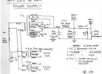
Indeed I've used PSU2 to simulate the power supply. Don't know what I'm doing wrong here, but the software predicts lower values HT values than the ones indicated at the schematics I'm using (280V instead of 320). (Schematics attached for reference).
For simulation, I'm charging the power supply with a constant load of 100ma, (Since each 2A3 are biased at around 53ma as far as I've calculated), and a cap of 100u insteaf of 47u in the Power Supply. Off load Transformer is estimated as 315 volts by the software.
One more question: I'm thinking of plugging the amp with no valves at all (even the rectifier tube left ou) to check the secondary voltages of the transformer (Yeah, I know I should have done that before soldering its leads). According to my circuit analysis, it should cause no harm at all and would be worth it to reveal the unknown. Any thoughts on this take?
Thank you.
Attachments
I'm thinking of plugging the amp with no valves at all (even the rectifier tube left ou) to check the secondary voltages of the transformer (Yeah, I know I should have done that before soldering its leads). According to my circuit analysis, it should cause no harm at all and would be worth it to reveal the unknown. Any thoughts on this take?
That's an excellent plan. Then, as a second step, you can add in the signal tubes and retest the heater voltages, just to be sure. Then add the rectifier and test for smoke!
All good fortune,
Chris
")
Hi!
Here is my advice how to test:
First check with the power turned off:
Measure DC resistance from each tube pin to ground and from each tube pin to B+ and see if the DCR reading corresponds with the expected values from the schematic.
If all reads ok, unplug all tubes and turn the power on. Measure heater voltages on the respective pins and the voltage on the tube rectifier plates.
readings will be higher than expected since the transformer is unloaded.
Then turn off and pug in the signal tubes. Turn on and check if the heater voltage is within limits ( I shoot for a range between nominal value and -5%)
You can do the same test for the rectifier tube and first unsolder the HV leads from the power transformer.
If all tests ok, power up with just the recitifer tube plugged in. Do this test only if your capacitors can handle the increased voltage! As has been mentioned the voltage will be substantially higher when the PSU is unloaded.
Alternatively, solder in a bleeder resistor which will draw enough current.
Measure the B+ voltage and also check if it arrives at the anode pins of signal tubes.
If that is also ok, test with all tubes installed. Measure cathode voltages and check if bias currents are within limits. Also measure all plate voltages.
If all static readings are ok, next test would be to run a frequency sweep to see if frequency response is ok.
Best regards
Thomas
- Status
- This old topic is closed. If you want to reopen this topic, contact a moderator using the "Report Post" button.
- Home
- Amplifiers
- Tubes / Valves
- Tips needed for some testing my newly built tube amp