Hello,
this is my first post in this forum. I know this subject is not new and there are many posts around this questions, and I went through many of them, but I'm still a little confused and would very much appreciate your opinions.
I'm considering an integrated amp (no line stage) with a c3g pentode direct coupled to a 6b4g, following the schematic posted by Thorsten:
http://www.diyaudio.com/forums/tube...d-single-ended-valve-amplifiers-part-1-a.html
I like the elegant approach with low parts count, and it suits well the parts laying in my drawer... and I'd like to explore the pentode-dht combination.
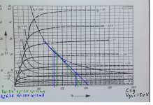
Now I'm trying to find a reasonable operating point for the c3g. I have taken the Telefunken datasheet http://www.shinjo.info/frank/sheets/128/c/C3g.pdf
and drawn tentative operating points on the curves for screengrid=150V (seems to be the "standard value"), as you can see in the attachment.
I started with operating point (green) Ua=220V, Ug2=150V, Ia=12mA, and anode load Ra=5k for a gain of ~70 (g3c transconductance is 14ma/V); this is a very low anode resistor value, bit still more gain than I probably need. My main concern here is that if the 6b4g is driven to full output (voltage swing 90Vpp), the current of the g3c anodes goes down to very low 3mA. Is this OK or would this raise slew rate distorsion issues? The Miller capacitance of 2a3/6b4g is even higher than that of 300b, so it's quite demanding here; on the other hand, direct coupling should lessen the requirements a bit? I would like to shift the quiescent operating point to higher current, but that would exceed the rated power dissipation limit.
So for stronger current drive I've chosen a second operating point (blue) with lower anode voltage: Ua=210V, Ug2=150V, Ia=15mA, and increased the anode load value to Rk=6.7k. Even higher gain..., but now the minimum anode current would be up to 8mA, still complying with the power dissipation limits and the rule "anode voltage should always be above screengrid voltage, plus some headroom", as Thorsten states in his writeup (anode 60V above screengrid, anode swing 45V amplitude).
So, which operating condition would be "better"? Well, the two operating are quite close, and perhaps wouldn't make much difference soundwise, so some of you might consider this a nit-picking question. But for me this is a kind of excercise as I would like to get more insight into this pentode thing...
And last but not least: I've never seen that lowish anode resistor values in similar applications, I feel quite alone here. Maybe this is because the distorsion shifts too much to the second harmonic /triode-like pattern, and if of one wanted this (and not too much gain as I do), triode wiring would be the way to go anyway. But I once have listened to a pentode > dht and liked it very much...
Thank you very much,
Miguel
this is my first post in this forum. I know this subject is not new and there are many posts around this questions, and I went through many of them, but I'm still a little confused and would very much appreciate your opinions.
I'm considering an integrated amp (no line stage) with a c3g pentode direct coupled to a 6b4g, following the schematic posted by Thorsten:
http://www.diyaudio.com/forums/tube...d-single-ended-valve-amplifiers-part-1-a.html
I like the elegant approach with low parts count, and it suits well the parts laying in my drawer... and I'd like to explore the pentode-dht combination.
Now I'm trying to find a reasonable operating point for the c3g. I have taken the Telefunken datasheet http://www.shinjo.info/frank/sheets/128/c/C3g.pdf
and drawn tentative operating points on the curves for screengrid=150V (seems to be the "standard value"), as you can see in the attachment.
I started with operating point (green) Ua=220V, Ug2=150V, Ia=12mA, and anode load Ra=5k for a gain of ~70 (g3c transconductance is 14ma/V); this is a very low anode resistor value, bit still more gain than I probably need. My main concern here is that if the 6b4g is driven to full output (voltage swing 90Vpp), the current of the g3c anodes goes down to very low 3mA.
Is this OK or would this raise slew rate distorsion issues? The Miller capacitance of 2a3/6b4g is even higher than that of 300b, so it's quite demanding here; on the other hand, direct coupling should lessen the requirements a bit? I would like to shift the quiescent operating point to higher current, but that would exceed the rated power dissipation limit. So for stronger current drive I've chosen a second operating point (blue) with lower anode voltage: Ua=210V, Ug2=150V, Ia=15mA, and increased the anode load value to Rk=6.7k. Even higher gain..., but now the minimum anode current would be up to 8mA, still complying with the power dissipation limits and the rule "anode voltage should always be above screengrid voltage, plus some headroom", as Thorsten states in his writeup (anode 60V above screengrid, anode swing 45V amplitude).
So, which operating condition would be "better"? Well, the two operating are quite close, and perhaps wouldn't make much difference soundwise, so some of you might consider this a nit-picking question. But for me this is a kind of excercise as I would like to get more insight into this pentode thing...
And last but not least: I've never seen that lowish anode resistor values in similar applications, I feel quite alone here.
Maybe this is because the distorsion shifts too much to the second harmonic /triode-like pattern, and if of one wanted this (and not too much gain as I do), triode wiring would be the way to go anyway. But I once have listened to a pentode > dht and liked it very much...Thank you very much,
Miguel
Attachments
Looking good, from what I read c3g is very linear. With this high current, slew rate is not going to be a problem.
Maybe use 6K8 load (more headroom), and decrease the current just a little, to increase life of this rare valve. The output stage should distort before the driver stage.
Maybe use 6K8 load (more headroom), and decrease the current just a little, to increase life of this rare valve. The output stage should distort before the driver stage.
You just crank it up till it turns red, then back it off a little.Looking good, from what I read c3g is very linear. With this high current, slew rate is not going to be a problem.
Maybe use 6K8 load (more headroom), and decrease the current just a little, to increase life of this rare valve. The output stage should distort before the driver stage.
Hi, thanks for your replies.
, but 6k8 isn`t very popular either... C3g is not rare at all at least here in Germany, they were produced in very large quantities. That does not mean that I'm willing to torture them
I`m not quite sure what you mean by the asymmetric output swing. I see that the control grid lines are not equidistant (as with the nice triode curves), so the input swing will not be amplified into a fully symmetric output swing. But I see this point in ALL pentode curves, and, if I stick to the g3c curves, I can't find an operating region where this looks better, at least within the allowed power dissipation and higher anode voltage area (for keeping it above the screengrid voltage for the entire swing cycle). Please tell me if I'm wrong.
I don`t know, there may be better choices, but it is used in this application in commercial designs such as Yamamoto (never heard any of their amps) and in diy designs. It seems to be a very high quality tube, and is easily available and cheap here in Germany.is such high gain device any good for a tough driver stage ?
well, yes, I'm still considering this, but if I went this route maybe there would be better options available?, E180F or d3a or ...but what if you lower the gain using it in pseudo triode ?
?? I would like to know... maybe it comes down to a question of taste? Opinions welcome.would it be a better driver then ?
yes, among the two depicted operating conditions, I'm tending to the higher load value. Apparently, nobody uses 5k loadMaybe use 6K8 load (more headroom), and decrease the current just a little, to increase life of this rare valve.
, but 6k8 isn`t very popular either... C3g is not rare at all at least here in Germany, they were produced in very large quantities. That does not mean that I'm willing to torture themYou are right, I don`t feel "fully comfortable", not at all. Btw, if anybody could direct me to a sort of tutorial of the kind "How to design pentode drivers", I would very much appreciate this. I couldn`t find anything substantial, that`s why I´m posting my newbie questions here.Both of your choosen working points give quite asymmeteric output swing. I get the impression you have not fully comfortable with use of Ua/Ia-diagrams.
I`m not quite sure what you mean by the asymmetric output swing. I see that the control grid lines are not equidistant (as with the nice triode curves), so the input swing will not be amplified into a fully symmetric output swing. But I see this point in ALL pentode curves, and, if I stick to the g3c curves, I can't find an operating region where this looks better, at least within the allowed power dissipation and higher anode voltage area (for keeping it above the screengrid voltage for the entire swing cycle).
Please tell me if I'm wrong.not yet determined. The driver stage will be fed from the main B+. Maximum available B+ is approx. 540V. Assuming that I need 305V for the 6b4g in typical autobias operating condition (295V anode to grid) plus let's say 10V OPT voltage drop, and the driver anode being direct coupled to the power tube grid, these 305V would be available for the combined voltage drop of the driver b+ voltage drop resistor and the driver anode load resistor, see R5 and R4 in Thorsten's schematic. There still remain max. ~235V for the driver anode potential above ground, more than I need probably, but lowering B+ is no problem. (Maybe I want to spend the "surplus" volts for pushing the 6b4g a little bit more.)What is your B+ of the driverstage?
As a very general rule, the higher your supply voltage the lower the distortion. Excess gain can always be traded for lower distortion with loop feedback and/or cathode resistor degeneration. It'll also give larger output voltage swings, perhaps allowing some degeneration or short loop feedback in succeeding stages. Just a thought.
All good fortune,
Chris
All good fortune,
Chris
yes, among the two depicted operating conditions, I'm tending to the higher load value. Apparently, nobody uses 5k load
You are designing by checking what is "trendy" ???
Let me put it this way: I don't feel confident yet, trying to learn from what others do, and if I find that a design idea seems quite uncommon such as the load issue, I question that an try to get to the bottom of it, as I might be missing something.You are designing by checking what is "trendy" ???
- Status
- This old topic is closed. If you want to reopen this topic, contact a moderator using the "Report Post" button.
- Home
- Amplifiers
- Tubes / Valves
- Need help for designing C3g pentode driver for 6b4g se