zoi,
For the star ground and center tap and safety house/earth ground, here's what it looks like should be done. (If anyone sees anything that might be wrong with anything I say, or have said, please jump in and correct it.)
The power transformer's center taps should connect to the ground side of the first smoothing capacitor (the one closest to the transformer, in the schematic). The main center tap will have closely followed the wiring through the rectification stage, to the first cap, already.
Use a good-sized bolt for the star ground point. Solder is not allowed, for connecting to the safety earth. It must be bolted or welded.
You will need circular lugs for connecting wires to the bolt.
I would locate the bolt about halfway between the last/leftmost smoothing capacitor and the input stage. But your mileage may vary.
Connect the cathode ground of the input section (from the signal ground under the leftmost tube on the schematic) to the bolt.
If you separated the signal grounds of the other stages, connect those to the bolt, first, and then connect the input stage's ground.
Then connect the safety earth house-wiring ground (not the "neutral"), from the third prong of your AC power plug, to the star ground bolt, using a very thick wire.
Then connect a wire from the last smoothing capacitor's ground to the bolt. (It looks like the original ground wire between the last smoothing cap and the input's signal ground was about right, after all.)
Later, if there is any residual hum, you could insert a "safety earth disconnect network" between the star ground and the safety earth ground from the AC power plug. To do that, you would probably just use two bolts: Remove the safety earth ground from the star ground bolt and put it on a new bolt and then connect the two bolts with the disconnect network. The wire lug for the diosconnect network would go on the star ground bolt in the same position where the safety earth had been.
The disconnect network is essentially two anti-parallel high-current diodes in parallel with a 10 Ohm resistor (and optionally a parallel .01uF to 0.1 uF AC-rated ceramic capacitor). The diodes would need to be able to carry 30 or 40 amps or more. So a lot of people just use a large bridge rectifier there, instead of two discrete diodes. You can find a lot more about them by doing some searches
Cheers,
Tom
Last edited:
Tom, there's a discrepancy on connecting to starground actually the last cap or the cap which has the highest current drawn. Practically it comes down to either presenting the lowest current to ground (your way) or shortening the distance between power and consumer (another way). Depending on the circuit one way or the other will be more convenient; we always want some distance between the pulsating PS and the electronics but we sometimes don't want to introduce extra inductance or resistance to the circuit.... Then connect a wire from the last smoothing capacitor's ground to the bolt.
An externally hosted image should be here but it was not working when we last tested it.
In this graphic point B goes to a driver tube. The driver and its components have the shortest connection to a local ground. The 32uF cap bypasses the 270uF cap and shares the connection of the driver stage to the (remote) star ground.
Maybe just say that the PSU should be grounded at its output? One could argue that the 32uF above is not part of the PSU but part of the amp. Minor point, and in most cases it probably doesn't matter whether you ground at the 270uF or the 32uF. Just don't ground the 6uF or the CT, as many people seem to do then wonder why they get buzz.
Tom, to be pedantic with most countries safety regulations, the protective earth from the mains socket should always go to an independant bolted connection to chassis, and not be a bolt used for physically supporting parts. Any star ground would be to a different chassis connection point.
Thank you all for your help. I never imagined getting such detailed and knowledgeable feedback.
By your suggestions, I have moved the rectifier tube to the other side next to the mains transformer and twisted a ground wire with the signal path through the first two stages. This greatly reduced the hum (by 85% or so). The level is nearly acceptable now.
Next, I will attempt to implement the rest grounding scheme you suggested and will update.
Many thanks for your kind help!
Tom, there's a discrepancy on connecting to starground actually the last cap or the cap which has the highest current drawn. Practically it comes down to either presenting the lowest current to ground (your way) or shortening the distance between power and consumer (another way). Depending on the circuit one way or the other will be more convenient; we always want some distance between the pulsating PS and the electronics but we sometimes don't want to introduce extra inductance or resistance to the circuit.
An externally hosted image should be here but it was not working when we last tested it.
In this graphic point B goes to a driver tube. The driver and its components have the shortest connection to a local ground. The 32uF cap bypasses the 270uF cap and shares the connection of the driver stage to the (remote) star ground.
disco,
That all sounds right. My main concern was to keep the capacitor charging currents that flow in a loop from the transformer secondaries to the center tap (through the caps) from polluting the star ground. That seems to imply that the star ground should be at or beyond the last cap. But I don't know how much it will matter. Also, what about putting it on a short "stub" of conductor, just off of the conductor between the 2nd and 3rd caps' grounds? That way, the caps' charging currents wouldn't need to flow through it.
Please allow me to zip out onto a tangent, for a few moments: I do understand about not wanting to introduce extra inductance into a power/ground path, by lengthening it. I am glad that someone else is concerned about that too, actually. But in that case why not have another capacitance, directly across the load? i.e. a decoupling cap. There is no other way to overcome the inductance of the power and ground conductors, unless they are less than about three centimeters, round trip.
(I suspect it's just the schematic, and that, like the grounding, maybe the caps are actually meant to be placed near certain tubes or in certain ways, but that is simply not shown on the schematic. But I'll press on with what I was going to say, anyway, because it might be interesting to someone besides just me.)
Think about a suddenly-demanded transient current. If the amplification device (tube, in this case) in question is capable of much slew rate at all, the worst-case transient current needed can't possibly get through several inches each way of power and ground inductances in time to accurately reproduce the transient. Even worse, during the attempt, a large voltage is induced across the rail inductances, even if the current has a very small amplitude, since the voltage induced across an inductance is proportional to the rate-of-change of the current, not its amplitude.
Many very smart people worry a whole lot about the decoupling capacitors across digital chips' power and ground pins. But I have found that it is also critical at audio frequencies, mostly for high-power active devices.
If you do the math to calculate how much local capacitance is needed JUST to be able to supply the transient currents, and then also calculate how much inductance can be tolerated in their connections across an active device (which determines the allowable round-trip connection length), it turns out that it's often very difficult to even physically get enough capacitance, with low-enough inductance, across the power and ground pins of a power audio device. Typically, one might be forced to use multiple smaller capacitors in parallel, just to get the inductance low-enough. And that implies that each capacitor has to have separate connections to the power and ground pins, since any mutual inductance prevents paralleling from lowering it as expected.
Anyway, I have a hunch that accurate transient response is a critical distinction that might separate the merely-great power amplifiers from the truly-exquisite ones. After all, almost any amp can be made to have low distortion for steady-state sine signals. So the crucial differences must be in the transient response.
I've got links to where I have started to derive the calculations for the decoupling capacitor stuff, if you're interested. They're very simple calculations, actually. Henry Ott and Bruce Archambeault have gone into such things in great detail, for high-speed digital PCBs. But I couldn't find where anyone had done anything similar for discrete-component audio circuits. I originally just wanted to know how to calculate the minimum required decoupling capacitance but it turned out to be a little more involved than I thought it would be. And then the results were surprising, and it looks like many DIY (and commercial) audio circuits don't do it well-enough.
Cheers,
Tom
Last edited:
Thank you all for your help. I never imagined getting such detailed and knowledgeable feedback.
By your suggestions, I have moved the rectifier tube to the other side next to the mains transformer and twisted a ground wire with the signal path through the first two stages. This greatly reduced the hum (by 85% or so). The level is nearly acceptable now.
Next, I will attempt to implement the rest grounding scheme you suggested and will update.
Many thanks for your kind help!
That's fantastic news! It's easy and fun to sit here and pontificate but it's gratifying to hear that it works. It would be great if you would let everyone know what else helps.
Maybe just say that the PSU should be grounded at its output? One could argue that the 32uF above is not part of the PSU but part of the amp. Minor point, and in most cases it probably doesn't matter whether you ground at the 270uF or the 32uF. Just don't ground the 6uF or the CT, as many people seem to do then wonder why they get buzz.
Good point, DF96. I sort of suspected, from disco's comments, that the 32 uF might be more like a decoupling cap that should be right by the tube. So then its ground connection would just be another part of the star.
Tom, to be pedantic with most countries safety regulations, the protective earth from the mains socket should always go to an independant bolted connection to chassis, and not be a bolt used for physically supporting parts. Any star ground would be to a different chassis connection point.
Thanks, trobbins. I, for one, appreciate pedantry.
I am, however, a bit surprised that AndrewT didn't beat you to it.
First, he needs a conductive chassis. Then, the safety earth ground from the wall outlet needs to connect to a dedicated bolt, i.e. for it only, in the chassis. The star ground connections need to go to a different bolt in the chassis.
Essential reading: Audio Component Grounding and Interconnection - diyAudio
As the article points out, the very term "ground" is problematic. It's better to separate the concept of "common" and "ground" (or "earth"). "Common" is the point where current returns to its source. Make sure you understand each separate current loop in the circuit. Draw the loops - really. At a star or buss, the commons for each loop are brought together.
If you have done this correctly, the practice of lifting the signal common will make little or no difference - though it won't hurt either. The commons can be lifted from the chassis earth, via a resistor.
BTW the commons don't necessarily have to be DC connected to the chassis earth, though they usually are (protects against a short between the power transformer primary and secondary).
Sheldon
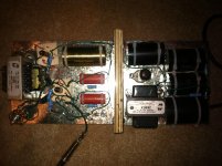
After a full rebuild on a metal chassis (pic attached), with the star grounding mostly as described above, here are the developments...
The hum is reduced but still there. HOWEVER, if I disconnect the heaters the hum instantly stops! This tells me all I need is a clean heater supply...
But now there is another problem.
After the rebuild, there is severe blocking distortion and the resistor bypassing the cathode bypass cap on the power stage (labeled 25uf on the schematic) is getting really hot! As the tubes warm up, a voltage appears across the cap (around 50vdc or so).
I have checked and double checked and everything is the same as it was. Did I damage a tube? Or a capacitor?
Attachments
After a full rebuild on a metal chassis (pic attached), with the star grounding mostly as described above, here are the developments...
The hum is reduced but still there. HOWEVER, if I disconnect the heaters the hum instantly stops! This tells me all I need is a clean heater supply...
But now there is another problem.
After the rebuild, there is severe blocking distortion and the resistor bypassing the cathode bypass cap on the power stage (labeled 25uf on the schematic) is getting really hot! As the tubes warm up, a voltage appears across the cap (around 50vdc or so).
I have checked and double checked and everything is the same as it was. Did I damage a tube? Or a capacitor?
The cap is dead, or unreliable at best. It should not conduct any current. For now, remove the cap. Measure the resistance of the cathode resistor. If that checks out, power up and measure the voltages at the plate, grid and cathode of the output tube. That will point to the problem.
Your noise may be due to a failing output tube - maybe not surprising if you check the maximum ratings for that tube.
Sheldon
Last edited:
Hope I can help first what is the tube compliment ? on the board . the 5902 is a sub minny with a max of 165 volts on the plate . I am at odds that the picture does not match the schematic . On the schematic replacing the r23 r24 100 ohms with say a 250 ohm center taped pot and take the tap to ground adjusting from side to side to get the quietest point . http://www.mif.pg.gda.pl/homepages/frank/sheets/141/5/5902.pdf Regards
- Status
- This old topic is closed. If you want to reopen this topic, contact a moderator using the "Report Post" button.
- Home
- Amplifiers
- Tubes / Valves
- Hum in homebuilt amp