Hi everyone.
I decided to built this tube amp 300B Mk1 Tube Amplifier but before I do it I have some questions about the design that I want to solve before I try it.
I've read some things about tubes and DHT tubes but I find it hard to understand some things.
1. If someone gives me the voltages of the anode, cathode etc. I can find everything easily. But if I want to design a tube amp like this I don't know where to start. I would like someone to explain what way is better to bias the tubes and what specifications of the tubes give me the voltages or everything else that I need. In other words I would like to know how can I use the datasheets when I want to design something because I am a llitle confused
2. I also find it hard to understand the combination of the 50Ω resistor and the 880Ω resistor and how this thing gives the 70 V of the cathode (I've read in other posts that the cathode operates about 70 volts)
And at last I think I must apologize for my bad English
Hi everyone.
I decided to built this tube amp 300B Mk1 Tube Amplifier but before I do it I have some questions about the design that I want to solve before I try it.
I've read some things about tubes and DHT tubes but I find it hard to understand some things.
1. If someone gives me the voltages of the anode, cathode etc. I can find everything easily. But if I want to design a tube amp like this I don't know where to start. I would like someone to explain what way is better to bias the tubes and what specifications of the tubes give me the voltages or everything else that I need. In other words I would like to know how can I use the datasheets when I want to design something because I am a llitle confused
2. I also find it hard to understand the combination of the 50Ω resistor and the 880Ω resistor and how this thing gives the 70 V of the cathode (I've read in other posts that the cathode operates about 70 volts)
And at last I think I must apologize for my bad English
Well yours is a long way from the worst I've seen on this forum; no need to apologise!
Since you can write as well as you have in English, I suggest you buy a copy of Valve Amplifiers by Morgan Jones; this book is an excellent introduction to the principles of designing valve amplifiers.
As for your second question, first the 50 ohm is a potentiometer across the filament terminals of the 300B; it is known as a hum balance or "humbucker" pot. When directly heated valves such as 300B are heated from an A.C. source hum can be induced owing to resistance variations in the filament. Adjusting the hum balance pot compensates for this effect. As the valve ages, further adjustment may become necessary.
70V at the cathode with 880 ohms is a simple application of Ohm's law where
V/R=I or V=IR where the voltage in a circuit bears a direct relationship to the resistance of the circuit and the current flowing. So in your example, divide 70V by 880 ohms = 0.0795 - say 0.080A = 80 milliamps, the current flowing through the 300B.
Paul
thank you for your quick reply.. so is 80mA good for this tube?
Learn to use the resources of the WWW to get data about various tubes. This time, I'll point you to a chart of 300B operating condition sets. Look here.
thank you for your quick reply.. so is 80mA good for this tube?
You are most welcome.
As for your question, I expect you have read Eli's reply with its very useful attachment.
Paul
I'd strongly recommend building this in a chassis with PLENTY of room in it. If this is going to be you "experimental" amp, leave room for improvements. An interstage transformer would be an instant improvement. There are also variations on the first stage like the 3a5 circuit from Rod Coleman on a recent 3a5 thread. You might also consider having the PSU in a different box so you only have DC in the signal chassis.
Have you chosen an output transformer? If you have a circuit that runs the 300b at 80mA, then you need an output transformer that is gapped for 80mA, or preferably slightly more. If you choose to buy an OPT gapped for 60mA, for example, you then have to change the cathode resistor on the 300b to run it at 60mA, or 50mA - use Ohm's law as 7N7 states. And yes - buy Morgan's book and read basic principles.
Andy
The 300B is not an easy tube to drive.
I build a 300B driver a while back. The design is available here: 300B Driver : Neurochrome.com : : Audio
I've also dabbled in a DC coupled version:
http://www.diyaudio.com/forums/tube...300b-idea-request-comments-3.html#post2440807
Right now, I'm experimenting with an ECC99 common cathode stage with a cathode follower output. That works really well.
I tend to run the 300B rather hot - 400 V, 90 mA. Just shy of the 40 W max plate dissipation.
~Tom
so after reading some articles I have more questions about the schematic.
I found EH 300B datasheet and tried to draw the load line and calculate the bias point. in the picture below I set the plate voltage at 360v (80% of Vplate max). With 880Ω resistor I have about 69volts dropped across cathode resistor and the bias current is ~80 mA. so the max current is 150mA. But if I draw the load line I don't have 2.5kΩ load as the schematic shows. So I suppose I am thinking-doing something wrong... Right?
I found EH 300B datasheet and tried to draw the load line and calculate the bias point. in the picture below I set the plate voltage at 360v (80% of Vplate max). With 880Ω resistor I have about 69volts dropped across cathode resistor and the bias current is ~80 mA. so the max current is 150mA. But if I draw the load line I don't have 2.5kΩ load as the schematic shows. So I suppose I am thinking-doing something wrong... Right?
Attachments
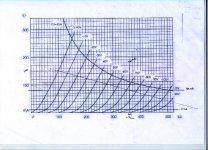
The line that crosses the Y axis at 100 mA and the X axis at 250 V is a 2.5 kOhm load line. That one is drawn correctly. It does not, however, intersect the quiescent/bias point of the tube in your amp, hence, it is not the load line as seen by the tube. Draw a line that is parallel to your 2.5 kOhm load line that goes through the quiescent point. This load line will also be a 2.5 kOhm load line (as it's parallel to the first 2.5 kOhm line you drew) but it goes through the Q point, hence, will be the load line for the output tube.
Does this make sense?
~Tom
Does this make sense?
~Tom
Last edited:
Does this make sense?
Yes it does make sense but if I do that the maximum current is about 240+ mA!!
So if the quiscient current is 80 mA the Q-point is not at the middle... right? and if this is right why does it happend? I think that in class A amplifiers the Q-point must be at the middle..
If your bias point is with the current at 80mA then the current can swing plus / minus 80mA maximum (and in reality a bit less than that). So the peak current flow would be just under 160mA.
I think you assumed that the grid would go to 0 volts. To swing the current from 0 to 160mA the grid will not need to go that far - with a 2.5k load line biased for 80mA idle, it would go no more positive than about -30 volts for 160mA current.
If you do take the grid more positive than -30 then you will simply introduce lots of distortion since the bias point would then not be at the middle of the current swing.
Last edited:
If you do take the grid more positive than -30 then you will simply introduce lots of distortion since the bias point would then not be at the middle of the current swing.
Ok I see what you mean.. But how can I be sure that the grid voltage wil not reach 0 or -10 volts?
so after reading some articles I have more questions about the schematic.
I found EH 300B datasheet and tried to draw the load line and calculate the bias point. in the picture below I set the plate voltage at 360v (80% of Vplate max). With 880Ω resistor I have about 69volts dropped across cathode resistor and the bias current is ~80 mA. so the max current is 150mA. But if I draw the load line I don't have 2.5kΩ load as the schematic shows. So I suppose I am thinking-doing something wrong... Right?
Not correct. If you drop 69 vols on the cathode resistor, this means that your HV (high voltage) will be 360-69 V, because ths is what the 300B "sees" between anode and cathode. So the center of the load line will be at the intersection of 291 volts with the 69Volts grid curve.
- Status
- This old topic is closed. If you want to reopen this topic, contact a moderator using the "Report Post" button.
- Home
- Amplifiers
- Tubes / Valves
- newbie questions about 300B tube amp