Hi all!
I'm quite a noob with tubes (built some chipamps, headphone amps and distortion pedals in the past), but wanted to try a tube amp also.
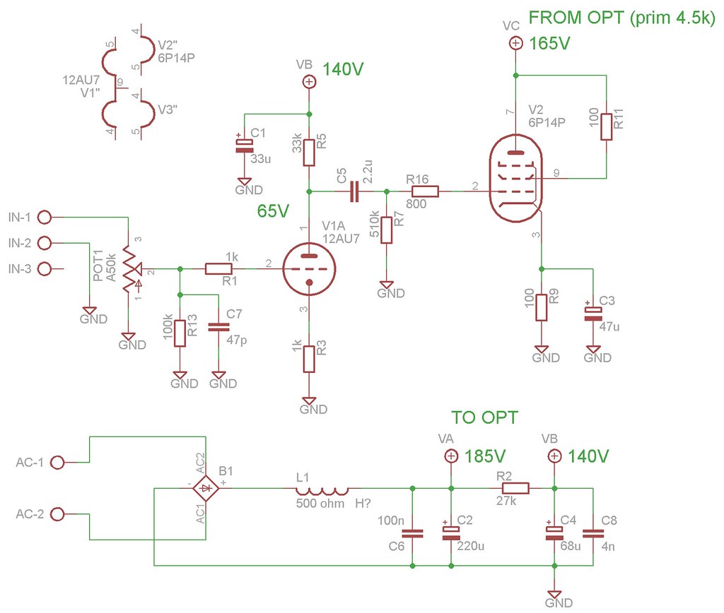
I'm currently testing my EL84 SE triode mode amplifier (6P14P to be exact), to get the most out of it before etching a pcb.
The OPT's are not ideal, they are 4,5k/4 ohm (Grundig from 50-60's), but they were really cheap from ebay. The power transformer is giving out 245V AC, this is lowered significantly by my "choke" (a winding of some soviet iron).
The amplifier is working ok and is even a pleasure to listen to.
I was wondering if anybody could give some advice to improve the amplifier further?
I'm quite a noob with tubes (built some chipamps, headphone amps and distortion pedals in the past), but wanted to try a tube amp also.
I'm currently testing my EL84 SE triode mode amplifier (6P14P to be exact), to get the most out of it before etching a pcb.
The OPT's are not ideal, they are 4,5k/4 ohm (Grundig from 50-60's), but they were really cheap from ebay. The power transformer is giving out 245V AC, this is lowered significantly by my "choke" (a winding of some soviet iron).
The amplifier is working ok and is even a pleasure to listen to.
I was wondering if anybody could give some advice to improve the amplifier further?
Hi all!
I'm quite a noob with tubes (built some chipamps, headphone amps and distortion pedals in the past), but wanted to try a tube amp also.
I'm currently testing my EL84 SE triode mode amplifier (6P14P to be exact), to get the most out of it before etching a pcb.
The OPT's are not ideal, they are 4,5k/4 ohm (Grundig from 50-60's), but they were really cheap from ebay. The power transformer is giving out 245V AC, this is lowered significantly by my "choke" (a winding of some soviet iron).
The amplifier is working ok and is even a pleasure to listen to.
I was wondering if anybody could give some advice to improve the amplifier further?
First, well done; it's good that you are enjoying the sound of your amplifier.
As for improvements, well you should increase the available HT; EL84 would be quite happy at 285-300V; you could aim for 35-40 mA at this voltage so as to operate the valve efficiently and at a good operating point.
Next I would bin the 12AU7; 12AU7 is not a good valve; satisfactory in old TV sets, and guitar amplifiers and that's it. Depending on the space you have, Ideally the best alternative would be the octal 6SN7 or the Loctal 7N7 (!) which is electrically the same. However these would require much higher supply voltage - about 400V is ideal with 47k load resistor. If you prefer to remain with lower voltages, then you could try ECC88 or the Russian 6N1P which is happy running at lower voltages. However 140V HT is really too low for any of the popular valves - including 12AU7!. You are running only 2mA through the 12AU7 and it needs to run quite a lot more than that. A higher supply voltage would mean that you could a) use a larger value of anode load and b) run more current through the valve.
Best of luck
Paul
Thanks for the reply Paul,
I have some 6N1P available (circuit needs to be adjusted to the pinout), I think I should try it. My power transformer gives 245V AC, to increase the voltage available after recification the best option seems to drop the choke and perhaps add another CR filter stage to make up for the noise increase.
Is this the right direction?
Your voltage is lower because of choke input. Change your PS to CL(RC) and you'll get some 250+ V if your power transformer has 230-250 secondary. See my schematic in post #22 at http://www.diyaudio.com/forums/tubes-valves/191691-1-stage-killer-literally-amp-made-junk-3.html. I mostly listen to it in triode with input directly to EL84 (yes, it is in the 50mW range but I still have to turn the volume down with speakers 1m away)Thanks for the reply Paul,
I have some 6N1P available (circuit needs to be adjusted to the pinout), I think I should try it. My power transformer gives 245V AC, to increase the voltage available after recification the best option seems to drop the choke and perhaps add another CR filter stage to make up for the noise increase.
Is this the right direction?
If there is now 185V at VA point in the schematic then moving the 220u cap in front of the choke would result in some 290V in the same place (assuming EL84s are biased at 40mA each)What would happen if a cap was placed in front of the choke I.e make a CLC filter?
Thanks for the reply Paul,
I have some 6N1P available (circuit needs to be adjusted to the pinout), I think I should try it. My power transformer gives 245V AC, to increase the voltage available after recification the best option seems to drop the choke and perhaps add another CR filter stage to make up for the noise increase.
Is this the right direction?
Yes that's good. When you get your higher voltage available, you will need to de-couple the supply from the output stage; a resistor and capacitor are the usual routes to this. You could run the 6N1p at about 80V meaning you could use a 47k or perhaps 39k anode load resistor depending on the HT you have available. I am sure this arrangement will sound much better.
Please ask if this is not clear.
Paul
Try modelling your power supply in Duncan power supplies simulator
[url=http://www.duncanamps.com/psud2/download.html]Download[/URL]
Loads of fun.")
RH84 is a good amp and uses the 12at7 ( ECC81 ) which is pin compatible to the 12au7 ( ECC82 ) Loads of Mullard 12at7's on Ebay for about £1.
Link to the RH84 for comparison, note the feedback.
RH 84 - Tube Audio ...... RH DESIGN
Your output transformers are within 10% of the 5k Ra normally used so should be fine. I've heard good things about Grundig OT's.
Capacitor C5 looks a bit high at 2.2uf, where did you get that value from?
HTH Bill
[url=http://www.duncanamps.com/psud2/download.html]Download[/URL]
Loads of fun.
RH84 is a good amp and uses the 12at7 ( ECC81 ) which is pin compatible to the 12au7 ( ECC82 ) Loads of Mullard 12at7's on Ebay for about £1.
Link to the RH84 for comparison, note the feedback.
RH 84 - Tube Audio ...... RH DESIGN
Your output transformers are within 10% of the 5k Ra normally used so should be fine. I've heard good things about Grundig OT's.
Capacitor C5 looks a bit high at 2.2uf, where did you get that value from?
HTH Bill
Last edited:
Thanks everyone!
7N7, what do you mean by de-coupling the supply from output stage? I thought I'm ok with a cap between 12AU7 and EL84? Could you post a link to some example.
Soonerorlater, I started with 47nF as C5, as there was not much bass I continued with 470nF, yesterday I changed it to 2.2uF, but it has no improvement over the 470nF, seems to be as good as it gets. I mean it's not bad at all and I realize the OPTs have there limits as well.
As a side note, I also tried some blue rectangular 470nF caps that sounded very bad, later I discovered the X2 marking on them
I have lurked around RH84 before, but as this is my first real tube project I would like to get it running optimally in SE triode with no feedback first, but I will seriously consider a feedbacked pentode mode as a switchable option. The purists might object, but I like a lot of switches on most of my devices
I have looked at 6N1P. Do I understand correctly, that it is ALMOST pin compatible with 12AU7, main difference being that the heaters of two halves are in series (not center tapped by pin 9 like 12AU7) and consume more current?
What to do with pin 9 of 6N1P?
Yes the heater current is higher. And only 6,3v possible.main difference being that the heaters of two halves are in series (not center tapped by pin 9 like 12AU7) and consume more current?
Pin 9 of 6N1P should be grounded. (Or rather may be grounded) You don't have to connect it to anything. But theoretically is should shield the 2 halves better if you have it connected to ground.
Last edited:
Hi all!
I managed to to raise the voltages a bit by moving the choke between the two electrolytics and changed the R2 to 6.3k and moved it between the last electrolutic and the tiny film cap.
Now the voltages from the PSU are 232V and 226V. It seems difficult to obtain much higher voltages if I leave this high resistance choke in there. (tried also without the choke, way too much mains hum)
I have also installed the 6N1P, I got the impression it sounds better than 12AU7, the frequency range seems a bit extended both ways. Now it appears, my preamp heater winding is a bit weak for 6N1P, gives only 5.8-6.1V depending on the 6N1P specimen. This winding has no specified current, the other one (used for 6P14P) has 3A written on it.
Could I consider heating all three tubes from the 3A winding?
One of my output tubes got bad, it started to distort on bass notes, had to replace it. These tubes likely have decades of TV duty behind them, I can't expect too much.
I should try to find another choke with less resistance, so I could get both voltages in the 250-300V range.
I remember an odd thing from a week ago when I changed the 12AU7 anode resistor values (20k, 33k, 47k, 100k), it had also a big influence to the 6P14P voltage going to OPTs. Of course the bias point of 12AU7 changed accordingly, currently it's around 166V with 6N1P.
Is this normal, or have I missed something?
As time passes I'm getting more and more joy out of this device
Of course safety is vital at these voltages, I armed myself with a capacitor discharge tool a couple of weeks ago.
Nice and clean design.
As people said about the PS filter, the voltage of your power transformer calls for C-L-C filtering.From first stage supply to second, an RC filter will do the decoupling, as you already have on the schematic ((R2/C4).
100nF first to second stage capacitor will probably be as good as it gets.
Recommended Grid stopper resistor for EL84 is 10Kohm, your mileage may vary of course.
Pin 9 of 6N1P is just a shield between the 2 sections, you should ground it. You are correct about the heater connectors.
Wire it up and light it up!
Could I consider heating all three tubes from the 3A winding?
This might be A helpful read........
The Valve Wizard
Soonerorlater, thanks!
That was some good reading. I'm thinking on artificial center tap, or a pot with the wiper as adjustabe center tap instead of the plain AC heater I'm using now.
One thing that seems strange.
The page suggests that heaters specified 6.3V can be run as low as 5V (80%) without signifficant negative consequences.
"Normal heaters rated at 6.3V can be run quite happily between 5V and 6.9V, maybe even lower, but not higher."
This picture, also posted somewhere on this forum, encourages rather some overvoltage.
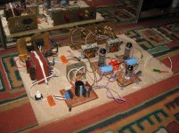
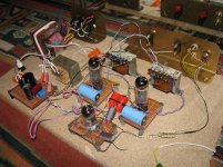
Just for the fun if it, here are some photos of this ugly thing.
The right edge of the particleboard was cut to measure by the stongest man in the village using brute force.
The machine is built of electronic waste, except for main power switch, some connectors and a few resistors.
The right edge of the particleboard was cut to measure by the stongest man in the village using brute force.
The machine is built of electronic waste, except for main power switch, some connectors and a few resistors.
Attachments
Hi all!
I managed to to raise the voltages a bit by moving the choke between the two electrolytics and changed the R2 to 6.3k and moved it between the last electrolutic and the tiny film cap.
Now the voltages from the PSU are 232V and 226V. It seems difficult to obtain much higher voltages if I leave this high resistance choke in there. (tried also without the choke, way too much mains hum)
Hi
Some observations: If I understand right you have 232V before, and 226V after R2. That means that your 6N1P's draw less than 1 mA together. Looking at the data sheet it seems that they shuold be run a 5+ mA to be reasonably linear.
Secondly, if your 500ohms value for the choke is correct and you have 232V after the choke then you are dropping close to 100V (depending on PT regulation) over 500 ohms. That indicates that you are drawing some 100mA per output tube!!!
Think you should check that out.
/Olof
tuhkam,
I think (from your post above) that you have miss-interpreted that graph.
It is saying that at 100% of heater voltage you get between 3,00 and 10,000 hours of tube life.
At 85% of heater voltage you get 3 hours tube life.
That is why all of the old text books and application notes specify plus or minus 5% maximum from nominal heater voltage.
For 6.3V rated heaters that means between 6.0 and 6.6 volts.
Cheers,
Ian
Hi
Some observations: If I understand right you have 232V before, and 226V after R2. That means that your 6N1P's draw less than 1 mA together. Looking at the data sheet it seems that they shuold be run a 5+ mA to be reasonably linear.
Secondly, if your 500ohms value for the choke is correct and you have 232V after the choke then you are dropping close to 100V (depending on PT regulation) over 500 ohms. That indicates that you are drawing some 100mA per output tube!!!
Think you should check that out.
/Olof
hemgjord, thanks for taking the time
the choke measures 500 ohm, when measured with a multimeter, I have no idea about the inductance. The resistance seems rather on the high side for a tubeamp choke?
I have another lonely output transformer that might qualify as a choke, that one measures around 350 ohm. Would this be more suitable?
In order to raise current draw of 6N1P should I decrease cathode resistor to 150 to 250 ohm? Or a change to anode resistor value to get to the 5mA?
On the output tubes, would doubling the cathode resistor value bring the current draw down to around 50mA?
The inductance of the choke is presenting an impedance which swamps it's dc resistance. This is what is causing the large voltage drop across the choke, along with the selected first cap. Increasing the value of the first cap will present less ripple to the inductor and a higher dc voltage resulting in a greater DC out.
Try placing a 2uF cap before the inductor.
Decrease the cathode resistor for the 6N1P and you will increase the current. You may need to change the anode resistor as well as the anode voltage will decrease due to greater voltage drop across the anode resistor at the higher current.
That said, I find that the 6N1P with a cheap red LED in the cathode (1.6-1.8V) works well and has low distortion even at low current. I use a .5-1mA adjustable current source and set the anode voltage around 115V.
- Status
- This old topic is closed. If you want to reopen this topic, contact a moderator using the "Report Post" button.
- Home
- Amplifiers
- Tubes / Valves
- EL84 SE advice for a beginner