Hi,
I don't know what the input and driver tubes are you're using but it seems a little complex just to drive a single 6C33C.
Than there's the feedback loop; not easy to implement correctly in SE amps and it kind of defeats the purpose for choosing the SE road in the first place IMHO.
Also the driver uses paralelled sections of a twin triode, this too isn't easy to make work correctly and any current hogging here will have a heavy penalty on detail resolution.
I don't want to discourage you at all but maybe it's worth to look for a simpler circuit.
Just trying ot help.")
Cheers,
I don't know what the input and driver tubes are you're using but it seems a little complex just to drive a single 6C33C.
Than there's the feedback loop; not easy to implement correctly in SE amps and it kind of defeats the purpose for choosing the SE road in the first place IMHO.
Also the driver uses paralelled sections of a twin triode, this too isn't easy to make work correctly and any current hogging here will have a heavy penalty on detail resolution.
I don't want to discourage you at all but maybe it's worth to look for a simpler circuit.
Just trying ot help.
Cheers,
fdegrove said:I don't know what the input and driver tubes are you're using but it seems a little complex just to drive a single 6C33C.
Yes, I'd like to see the types too. What's complicated about it? You need 80V into 150k, a 12AX7 isn't going to do it both due to low drive and that stigma on it, same for a pentode (although a 12BY7 would probably work, dunno about gain). And a single medium triode (6SN7 et al) doesn't have enough gain. That leaves using two stages.
Than there's the feedback loop; not easy to implement correctly in SE amps and it kind of defeats the purpose for choosing the SE road in the first place IMHO.
Also the driver uses paralelled sections of a twin triode, this too isn't easy to make work correctly and any current hogging here will have a heavy penalty on detail resolution.
So put some 100 to 470 ohm resistors in the cathodes. I don't see what's wrong with paralleling tubes, same thing goes on in the tubes themselves in an infinite way.
Tim
> Any comments welcome
You asked....
How much distortion does that second stage make? The penciled "114Vpk" appears to be "at clipping", if this stage runs on the +245V supply. I suspect it will exceed 5%THD at 50Vpk, which is less than your output stage needs.
In general, driving a triode with Mu of less than 5 is "not possible" when the driver stage runs on the same B+ as the output stage. The grid-swing of a low-Mu tube is too large to be driven from the plate swing of any reasonable R-C coupled driver working on the same supply voltage.
That's maybe not a problem. I don't think you will get 20 clean watts, but the FE208 series speaker will make a hell of a noise with a lot less than the full 20 watts.
The only reason I can see for 10K and 7.7K plate resistors (and paralled tubes) in voltage amplifiers is to get very wide-band response so you can put lots of negative feedback around it, up to 26dB NFB in the notes. I like NFB too. But with 26dB NFB around an amp, "all amps sound the same"; why bother with the size and heat of an SET?
Hi,
I said "complex" (it's overly complex in fact) which doesn't mean complicated.
In fact you could easily kick that big tube tube with a dissimilar triode, a 6EM7 or similar.
There are at least a dozen alternative including trioded penthodes to drive the powerstage.
Gain > Power > Power.
And I agree with PRR, this kind of amp is better off with a dedicated PS for input and driver.
I see you're a little puzzled by my rejection of global NFB...
Why use it when you don't need it?
When designed correctly I'm convinced you won't need it here and with the Fostex the amp will barely need to ever put out more than a few Watts.
Cheers,
What's complicated about it?
I said "complex" (it's overly complex in fact) which doesn't mean complicated.
In fact you could easily kick that big tube tube with a dissimilar triode, a 6EM7 or similar.
There are at least a dozen alternative including trioded penthodes to drive the powerstage.
Gain > Power > Power.
And I agree with PRR, this kind of amp is better off with a dedicated PS for input and driver.
I see you're a little puzzled by my rejection of global NFB...
Why use it when you don't need it?
When designed correctly I'm convinced you won't need it here and with the Fostex the amp will barely need to ever put out more than a few Watts.
Cheers,
Sch3mat1c is right. The circuit is about as "simple" as it could be without resorting to pentodes, "wasting" half a dual triode or using a more exotic second tube. Remember morfeas' is probably designing around what he has at hand, as many of us do...
Global NFB has it's applications. SET afficionados and tube purists frown on it. Hell even I steer clear whenever possible. But it has it's merits in certain circuits and can even improve sound in selected cases...
Global NFB has it's applications. SET afficionados and tube purists frown on it. Hell even I steer clear whenever possible. But it has it's merits in certain circuits and can even improve sound in selected cases...
Hi,
Now you have me frowning upon you here...
Wouldn't you agree it's a little early to make final judgements on this?
Can't make up your mind?
Cheers,
Sch3mat1c is right. The circuit is about as "simple" as it could be without resorting to pentodes, "wasting" half a dual triode or using a more exotic second tube. Remember morfeas' is probably designing around what he has at hand, as many of us do...
Now you have me frowning upon you here...
Wouldn't you agree it's a little early to make final judgements on this?
Global NFB has it's applications. SET afficionados and tube purists frown on it. Hell even I steer clear whenever possible. But it has it's merits in certain circuits and can even improve sound in selected cases...
Can't make up your mind?
Cheers,
fdegrove:
Please be more specific. What are you frowning about? Which judgement? What should I make my mind up about? Is the circuit complex, overly complex or complicated in your opinion? What is the difference between these three?
What have I given you to frown about? Try smiling.Now you have me frowning upon you here...
Which judgement are you referring to?Wouldn't you agree it's a little early to make final judgements on this?
Can too!Can't make up your mind?
Please be more specific. What are you frowning about? Which judgement? What should I make my mind up about? Is the circuit complex, overly complex or complicated in your opinion? What is the difference between these three?
Hi,
That people jump to conclusions without so little as a circuit diagram not even mentioning the tubes used bar the powertube or any other reason for the design choices.
When you say " he's probably using stuff he's got in his junkbox", how can you know?
How can you say Schematic3 is right with so little data to go on? I sure can't.
You actually say he's right and then say in the same sentence you say you try to stay away from global NFB yourself??
When I say in post #5 that the whole shebang can be reduced to the mininum, doesn't need GNFB, doesn't need // triode sections with all their potential problems, yes, I do frown.
Not that I want to start a flame war on this, mind you.
See the smile?
Please be more specific. What are you frowning about? Which judgement? What should I make my mind up about?
That people jump to conclusions without so little as a circuit diagram not even mentioning the tubes used bar the powertube or any other reason for the design choices.
When you say " he's probably using stuff he's got in his junkbox", how can you know?
How can you say Schematic3 is right with so little data to go on? I sure can't.
You actually say he's right and then say in the same sentence you say you try to stay away from global NFB yourself??
When I say in post #5 that the whole shebang can be reduced to the mininum, doesn't need GNFB, doesn't need // triode sections with all their potential problems, yes, I do frown.
Not that I want to start a flame war on this, mind you.
See the smile?

fdegrove: Morfeas was inviting informed opinions on his design idea. He doesn't need to justify his design choices to us.
To get enough gain/swing to drive the 6c33 using triodes at conventional tube voltages he must use 2 stages cascaded. There is no other way, barring pentodes, an exotic high-voltage cascode or a step-up tranny/choke. Therefore this circuit is simple, not complex. If you have a simpler driver circuit I would like to see it.
The use of parallel tubes does not cause "a heavy penalty in detail resolution" as you allege. Many PP, several SE and most solid state amps parallel output devices... And as Sch3mat1c pointed out a simple cathode resisitor will force current sharing. Advantages to be had include reduced Zout and dissipation.
I can't. That's why I said "probably"...When you say " he's probably using stuff he's got in his junkbox", how can you know?
Because it's obvious. The drive requirements of the 6c33, gain limitations of triodes and circuit voltages don't leave much room for creativity.How can you say Schematic3 is right with so little data to go on? I sure can't.
NFB in this application will improve speaker damping and could reduce OPT non-linearity. Which might actually IMPROVE the final sound... I repeat, if you have a significantly better or less complex answer then show us...When I say in post #5 that the whole shebang can be reduced to the mininum, doesn't need GNFB, doesn't need // triode sections with all their potential problems, yes, I do frown.
First of all, thanks for the interest. Your apologies for my delayed response.
First three triode sections are ½+1 6N1P.
The design is based on stick to the basics but with some crucial things in mind:
1. Symmetric slew rate all over stages (mean symmetric swing capabilities in every grid)
2. Each stage capable of exactly symmetrical clipping (toward positive and negative signal)
3. In the simulation you see the output stage needs only 10V/Ms slewing in the grid to produce a very good pattern of harmonic distortion (third harmonic is calculated to be 1/10th of second)
4. The overall open loop gain is about 53db. With that in mind you can use this amp as integrated with a very moderate feedback. But if you need to drive a load that needs some damping factor you have to put some more NFB. The safety margin of this circuit is about 50% (that means you can put 24-28db of NFB).
5. The other trick in the circuit is the Hammond 1640. You have the opportunity to use 3 different configurations. By using 4,8,16ohms taps you can make the primary winding load (that tube sees) 300,600 or 1200. From my experience I do trust their iron to the last Hz.
6. All stages are capable of very wide freq. response but as you see in the schematic the calculated dominant poles of the upper freq (high) are descending by factor of 2.
7. The first stage can handle about 2.5 rms input without any sign of clipping.
Some thinks look simple but are not simpler than thinks need to be.
Friends let’s stick to the basics.
MR. KNOW IT ALL...
Hi,
So? Where did I say any different?
Wake up. I already described in pst # 5.
Seems you only come here to argue, no?
I see. To me other things are obvious.
Speaker damping from a SET? That'll be the day.
I repeat, read the thread once more and you'll see.
Guess you didn't want to read this one either?
Cheers,
Hi,
To get enough gain/swing to drive the 6c33 using triodes at conventional tube voltages he must use 2 stages cascaded.
So? Where did I say any different?
If you have a simpler driver circuit I would like to see it.
Wake up. I already described in pst # 5.
Seems you only come here to argue, no?
Because it's obvious.
I see. To me other things are obvious.
NFB in this application will improve speaker damping
Speaker damping from a SET? That'll be the day.
I repeat, if you have a significantly better or less complex answer then show us...
I repeat, read the thread once more and you'll see.
Not that I want to start a flame war on this, mind you.
Guess you didn't want to read this one either?
Cheers,
> only come here to argue, no?
Both of you, cut it out.
morfeas proposed an interesting design, and you two have fallen into extended illogical nit-picking of each other. The last several messages add nothing to the discussion of morfeas's plan and just clutter the board with crap.
Go pick each others' nits in private.
Both of you, cut it out.
morfeas proposed an interesting design, and you two have fallen into extended illogical nit-picking of each other. The last several messages add nothing to the discussion of morfeas's plan and just clutter the board with crap.
Go pick each others' nits in private.
Hi,
I'm able to control this all by myself, thank you.
Ciao,
Both of you, cut it out.
I'm able to control this all by myself, thank you.
Ciao,
Some late comments, (sorry if most of it seems very negative)
In the simulation result I see that Gm for the output tube is given as 10.9mA/V, this seem strange if we are talking about a 6C33C which has Gm of 40mA/V, or maybe Gm as given here is not the tube Gm itself or min Gm at very low currents?
Also the plate curves shown look strange to me, according to the information I have, (also confirmed by measurements) the current at -1.65V grid and 51.4V plate is closer to 650mA then the 350mA seen here.
The gridstopper of the second stage seems to be very high, 10k is this really necessary? I always try to design without gridstoppers and only put them in as a last resort.
I understand that you aim for having very high bandwidth in all gain stages which I personally think is a very good idea in for example an OTL amp or preamp but in this case the output transformer will determine the overall bandwidth so I dont see it as necessary here.
I attach a schematic of a 6C33C SE amp I bought as a kit some years ago in Japan, this uses a cathode follower as driver for the 6C33C with totally 570V between Anode and cathode resistor, this way of driving a 6C33C in SE configuration has been used by many Japanese manufacturers with success.
Feedback is applied from the second stage to the input stage but not over the output stage.
The output power is 13W and the output transformer impedance is 600 ohm. The sound of this amplifier was very nice but a bit too soft for my taste and since stop using this amp I only build OTL amps.
http://www2.gol.com/users/tube/se.html
Regards Hans
...neither complex nor complicated...
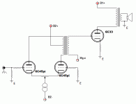
By way of taking up the challenge of driving the 6C33 from a single stage and acheiving the gain required, I knocked up the following schematic over lunch. It is based on my 845SE amp that I showed here. Actually using the 6C45pi gives too much gain if source is a CD player - so I would use either 6N1P in pp or my present favourite where greater than mu=20 is concerned, the C3g in triode mode (thanks Brett!)
The CCS can be any of the ones shown here and it's use allows the LTP to do the phase spliting with good balance. In practice I would use an input trannie phase splitter - but that is just me
I heard a 6C33 amp a couple of weeks ago and it had very good bass and dynamics but, to my mind, wasn't up to DHT in the mid-band and treble. Maybe it needs a DHT driver? In which case a pair of Aa DHTs in pp would be nice!!!
ciao
James
Attachments
Less complex and complicated
> ...neither complex nor complicated...
Less complex and complicated:
If the simulation run is accurate (or close), we "only" need 85V Pk in 200KΩ. We need a gain of a little more than 40 to reach the level that most preamps can easily deliver.
Gain of 40 suggests, to my super-simple mind, the good/bad-old 12AX7. But can it hack the job?
Rules-o-thumb: B+ should be 5 times the desired peak swing. Plate resistor should be 5 to 10 times smaller than the next grid resistor, or 2 to 5 times larger than the valve plate resistance, or if that doesn't work out try the geometric mean of plate resistance and grid resistor.
85V Pk swing suggests a B+ of 425V or more. Take 50K or 100K as a plate load resistor.
Other thumb rule: plate should sit at about 1/2 to 2/3rds of B+ for good swing with good gain and good distortion. This can be fudged one way or the other depending, but is a starting point.
So take B+ = 450V (which might be derived from a voltage-doubler on the main supply), set the plate at 1/2 to 2/3 is 225 to 300V.
Gain in that condition is about 40 or 50, perhaps allowing a whisper (1dB or 2dB) of NFB. (If the goal is large NFB, this won't do; but an SET can work fine with little or no NFB.)
Lookit: one rather ordinary tube to drive both channels. Can't get much simpler.
Yes, I know the 12AX7 has a bad reputation in some hi-fi cliques. Keep an open mind: the 12AX7 is often run rather lean and low, almost never hot and fat like this. It is going to sound like a different tube than most 12AX7 designs. Maybe it still sucks, maybe not.
SPICE analysis (don't trust SPICE too much):
That is just the 12AX7; I'm too lazy to model a 6C33 too. But the main distortion in both is 2nd order, in opposite ways, so there should be some distortion cancellation. It would not surprise me if 2% in the 12AX7 and 2% in the 6c33 came out under 2% overall.
Wiring around plate and grid has to be tight and neat: just 100pFd stray capacitance drops the -3dB point to 30KHz. This of course is always the problem when trying to get large gain with high impedances. HF -3dB point is also an issue with any transformer coupled driver design.
Supplying the +450V is a nuisance. I submit that a voltage doubler or a small plate-power transformer is cheaper than an audio transformer, and cleaner than almost any non-transformer/choke design working on the same supply as a low-Mu triode power amp.
I do agree that the transformer coupled design has elegance, can have nice round tone, and can be much more power-efficient than any resistance coupled design. If good plate-grid transformers were readily available at good price, and if feedback is not desired, the tranny is an obvious winner. The James 2-tube plan adds the cost of a tube section but significantly reduces the cost of a "good" transformer since there is no DC current to handle.
> ...neither complex nor complicated...
Less complex and complicated:
If the simulation run is accurate (or close), we "only" need 85V Pk in 200KΩ. We need a gain of a little more than 40 to reach the level that most preamps can easily deliver.
Gain of 40 suggests, to my super-simple mind, the good/bad-old 12AX7. But can it hack the job?
Rules-o-thumb: B+ should be 5 times the desired peak swing. Plate resistor should be 5 to 10 times smaller than the next grid resistor, or 2 to 5 times larger than the valve plate resistance, or if that doesn't work out try the geometric mean of plate resistance and grid resistor.
85V Pk swing suggests a B+ of 425V or more. Take 50K or 100K as a plate load resistor.
Other thumb rule: plate should sit at about 1/2 to 2/3rds of B+ for good swing with good gain and good distortion. This can be fudged one way or the other depending, but is a starting point.
So take B+ = 450V (which might be derived from a voltage-doubler on the main supply), set the plate at 1/2 to 2/3 is 225 to 300V.
Gain in that condition is about 40 or 50, perhaps allowing a whisper (1dB or 2dB) of NFB. (If the goal is large NFB, this won't do; but an SET can work fine with little or no NFB.)
An externally hosted image should be here but it was not working when we last tested it.
Lookit: one rather ordinary tube to drive both channels. Can't get much simpler.
Yes, I know the 12AX7 has a bad reputation in some hi-fi cliques. Keep an open mind: the 12AX7 is often run rather lean and low, almost never hot and fat like this. It is going to sound like a different tube than most 12AX7 designs. Maybe it still sucks, maybe not.
SPICE analysis (don't trust SPICE too much):
Code:
 HARMONIC   FREQUENCY    FOURIER    NORMALIZED
    NO         (HZ)     COMPONENT    COMPONENT
     1     1.000E+03    85.10       1.000E+00
     2     2.000E+03    1.935       2.274E-02
     3     3.000E+03    0.5282      6.207E-03
     4     4.000E+03    0.0431      5.070E-04
     5     5.000E+03    0.1213      1.425E-03
     TOTAL HARMONIC DISTORTION =   2.369417 PERCENT
That is just the 12AX7; I'm too lazy to model a 6C33 too. But the main distortion in both is 2nd order, in opposite ways, so there should be some distortion cancellation. It would not surprise me if 2% in the 12AX7 and 2% in the 6c33 came out under 2% overall.
Wiring around plate and grid has to be tight and neat: just 100pFd stray capacitance drops the -3dB point to 30KHz. This of course is always the problem when trying to get large gain with high impedances. HF -3dB point is also an issue with any transformer coupled driver design.
Supplying the +450V is a nuisance. I submit that a voltage doubler or a small plate-power transformer is cheaper than an audio transformer, and cleaner than almost any non-transformer/choke design working on the same supply as a low-Mu triode power amp.
I do agree that the transformer coupled design has elegance, can have nice round tone, and can be much more power-efficient than any resistance coupled design. If good plate-grid transformers were readily available at good price, and if feedback is not desired, the tranny is an obvious winner. The James 2-tube plan adds the cost of a tube section but significantly reduces the cost of a "good" transformer since there is no DC current to handle.

- Status
- This old topic is closed. If you want to reopen this topic, contact a moderator using the "Report Post" button.
- Home
- Amplifiers
- Tubes / Valves
- 6c33 Se