Who said the 6C33 must work at 40 Watts Pa ? Why ?
I gave an example where dissipation is ~44W, (220V, 200mA) which is what seems to be used in most Japanese designed SE amps with 6C33C. The experience from Japanese users and from others, (e.g. BAT) who have used/are using 6C33C is that running this tube on max dissipation increases the risk for failure and also increases the risk for socket failure due to overheating.
I have run my SET with 6C33C more than 6 years with no failure in tubes or sockets and the same goes for my OTL amp that I have used ~5 years with the same tubes and without adjustment.
However it is easy to find stories regarding 6C33C where either the tube or the socket have failed prematurely and I believe this is either due to too high dissipation or/and lack of using correct burn in or switch on procedures.
Regards Hans
Ari,
What's your opinion on this amp:
http://www.jogis-roehrenbude.de/Leserbriefe/Roessler-6C33-Amp/Beschreibung.htm
Thanx,
Franco
What's your opinion on this amp:
http://www.jogis-roehrenbude.de/Leserbriefe/Roessler-6C33-Amp/Beschreibung.htm
Thanx,
Franco
hi,
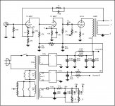
this circuit was I got from japan, I did it already. reallu sound good & easy to funish.
it running at 200V 200ma.
At first I prepare to use two tubes in one channel, but when I try to match the 6c33. Its not easy to match. So at last I tried this circuit.
thx
thomas
this circuit was I got from japan, I did it already. reallu sound good & easy to funish.
it running at 200V 200ma.
At first I prepare to use two tubes in one channel, but when I try to match the 6c33. Its not easy to match. So at last I tried this circuit.
thx
thomas
Attachments
Dear Hans,
You are right to say that one must not push the tubes to their limits. However, this is how I use them.
The 6C33 seem to be sturdy valves. The advantage is that I get
15-16 Watts ( 11 V RMS on 8 ohms ) with one tube.
Maybe I am less concerned because I have two dozen of 6C33 that I bought at good prices.
And maybe one of these days the valves I am using will give up.
Regarding the pilot section, I must add that I used ( again ) just one 6SN7GT to drive three 6C33s in parallel, to get 50 W ( 20 V RMS on 8 ohms ) of power. You can find the article, schematics a
Konnichiwa,
Funny, I got that much out of a 300B run near design center maximum ratings (direct coupled circuit, regulated PSU), must be that weedy joke of driver valve (6SN7) that limits the swing and power you get.
Sayonara
ari polisois said:You are right to say that one must not push the tubes to their limits. However, this is how I use them.
The 6C33 seem to be sturdy valves. The advantage is that I get
15-16 Watts ( 11 V RMS on 8 ohms ) with one tube.
Funny, I got that much out of a 300B run near design center maximum ratings (direct coupled circuit, regulated PSU), must be that weedy joke of driver valve (6SN7) that limits the swing and power you get.
Sayonara
Konnichiwa,
Ahh, so in your Amp the Output transformer is not coupled with a capacitor? What do you use in the powersupply?
Sayonara
ari polisois said:I would like parafeed if you did not have to couple the choke to the OPT with a capacitor !
Ahh, so in your Amp the Output transformer is not coupled with a capacitor? What do you use in the powersupply?
Sayonara
Konnichiwa,
Here the schematic.Values are omitted on purpose.
300B operated at 400V/95mA/2K4 load. Main +B series regulated with 6AS7 & E810F Erroramp, pasitve supply for super mu follower and negative driver voltage contained mosfet shunt regulators.
The 300B Grid could be driven significantly positive. Under these extreme conditions I measured 18 Watt RMS before hard clipping (ThD probably around 5%), using Svetlana 300B's.
As I usually did not need anywhere near that power I tended to connect the Output transformer for around 4K primary impedance and used 350V/60mA.
I have also taken the liberty to highlight the "coupling capacitor" when using series feed.
If we argue about "how bad" coupling capacitors are, I suspect the few uF used in parallel feed are infinitly preferable to a big value powersupply electrolytic.
Of course, that is not the end of the story in series and parallel feed, but as you claimed the probelm with parallel feed was the coupling capaictor I was surprised to see you using very poor quality coupling capaictors in your series feed circuitry. Of course, it seems most people are "powersupply blind"....
Sayonara
ari polisois said:Maybe the best way to judge is to have the schematics you
are referring to ( Super 300B and Parafeed ) compared in every detail.
Here the schematic.Values are omitted on purpose.
An externally hosted image should be here but it was not working when we last tested it.
300B operated at 400V/95mA/2K4 load. Main +B series regulated with 6AS7 & E810F Erroramp, pasitve supply for super mu follower and negative driver voltage contained mosfet shunt regulators.
The 300B Grid could be driven significantly positive. Under these extreme conditions I measured 18 Watt RMS before hard clipping (ThD probably around 5%), using Svetlana 300B's.
As I usually did not need anywhere near that power I tended to connect the Output transformer for around 4K primary impedance and used 350V/60mA.
I have also taken the liberty to highlight the "coupling capacitor" when using series feed.
If we argue about "how bad" coupling capacitors are, I suspect the few uF used in parallel feed are infinitly preferable to a big value powersupply electrolytic.
Of course, that is not the end of the story in series and parallel feed, but as you claimed the probelm with parallel feed was the coupling capaictor I was surprised to see you using very poor quality coupling capaictors in your series feed circuitry. Of course, it seems most people are "powersupply blind"....
Sayonara
The advantage is that I get 15-16 Watts ( 11 V RMS on 8 ohms ) with one tube.
This seems low, I got 13W RMS, (measured) with one tube at 220V and 200mA, I also have seen people mentioning up to 20W when running the tube at max dissipation. I use a 12BH7 CF direct coupled to drive the tube but as you say a 6SN7 should be enough if the tube is not driven to grid current as the input capacitance of the tube is not that high.
Regards Hans
Dear Kuey Yang,
Your circuit is OK.
If you look closely, it is a DCMB, where the load is the valve.
Regarding the parafeed I still disagree.
Admitting there is nothing to do with regard to the power supply electrolytics ( a necessary evil, unless you use batteries or sun cells), in the parafeed you have a second corrupted obstacle in the signal path of the power stage, the coupling capacitor.
No matter of what quality you choose it, it is still there, with its phase shifting and frequency discrimination.
You should read Menno van der Veen's studies on this subject.
As far as the shunt capacitors I have chosen to HF bypass the electrolytics, these were suited to the philosophy of the design, intended mainly to show how simple a SE amp can become, without being second class, but also without spending too much money in aristocratic capacitors. The manufacturers of such components are very active and no doubt those that can afford it, can replace any suggested capacitor by the high class ones, after reading their ads.
Sayonara
Hi,
Thank you.
No, it is not. If you look closely, it is a modified Loftin White. BTW, the Circuit is rather old. I messed with that stuff almost 10 Years ago.
You may diasgree, but that does not change the facts.
Now this is what I call "counterfactual argumentation".
Lets take "ideal" parallel feed and ideal series feed, okay?
In ideal series feed an ideal choke (infinite inductance) in parallel with a load resistor forms a current loop with the output valve, in whose anode circuit the choke/load resistance combo is placed. The choke blocks all signal current which has to pass through the
The current loop is clsoed through the Powersupply, the powersupply is in series with the signal and in fact, the power supply (capacitor) couples the signal on the +B side of the load Choke/Resistor combo to the valves cathode and is thus in the literal sense the coupling capacitor.
In ideal parallel feed circuit we have a load resistor coupled by a capacitor to the anode of the output valve. An (ideal) choke supplies the anodic current, but blocks all signal current from entering the powersupply, all signal current is returned to the cathode through the coupling capacitor and resistor.
Surely you will agree that in both cases the function of the capacitor with regards to the signal is the same? Of course, in our ideal example we have ideal capacitors too, so it matters not.
Now in a real circuit we have a different situation.
In series feed applications the coupling capaitor is also the last filter capacitor of the powersupply, it does double duty. Large values are needed which usually translates into poor quality. The choke is of limited inductance as well.
In parallel feed our coupling capcitor only does coupling duties and thus requires a dfairly small value (several uF). This usually allows a quite a high quality capacitor to be used. The anode load choke must be of large enough value not to redirect any signal away from the output load, so the inductance will usually be larger than that of the series feed output transformers primary inductance, thus no or very little signal enters the powersupply and if it does, it returns only severely attenuated, so no signal passes through the powersupply.
One would think that this state of affairs would be blindingly obvious to anyone who has grasped the basics of electronics (Ohm, Kirchoff, Lenz).
Of course, this is by far from the only issue in the parallel feed vs. series feed debate, but anyone who claims that parallel feed has a "coupling capacitor" that series feed lacks should kindly take remedial EE101.
On what subject? Has Menno now managed to proove any of the basic laws of Electronics inoperational? That is news, please provide a reference of this.
I am not sure how the above missive is relevant in context. However, you are no doubt aware that it has illustrated many times that electrolytic capcitors produce magnitudes higher levels of distortion compared to quality film types (such as are employed usually for parallel feed circuits), measurable and audible.
Counterfactual argumentation and name dropping will not make these basic facts go away. If you feel that the quality of the coupling capacitor in the output current loop of the SE Amplifier is of the main importance than parallel feed offers immesurably superior performance potential.
Sayonara
ari polisois said:Your circuit is OK.
Thank you.
ari polisois said:If you look closely, it is a DCMB, where the load is the valve.
No, it is not. If you look closely, it is a modified Loftin White. BTW, the Circuit is rather old. I messed with that stuff almost 10 Years ago.
ari polisois said:Regarding the parafeed I still disagree.
You may diasgree, but that does not change the facts.
ari polisois said:Admitting there is nothing to do with regard to the power supply electrolytics ( a necessary evil, unless you use batteries or sun cells), in the parafeed you have a second corrupted obstacle in the signal path of the power stage, the coupling capacitor.
No matter of what quality you choose it, it is still there, with its phase shifting and frequency discrimination.
Now this is what I call "counterfactual argumentation".
Lets take "ideal" parallel feed and ideal series feed, okay?
In ideal series feed an ideal choke (infinite inductance) in parallel with a load resistor forms a current loop with the output valve, in whose anode circuit the choke/load resistance combo is placed. The choke blocks all signal current which has to pass through the
The current loop is clsoed through the Powersupply, the powersupply is in series with the signal and in fact, the power supply (capacitor) couples the signal on the +B side of the load Choke/Resistor combo to the valves cathode and is thus in the literal sense the coupling capacitor.
An externally hosted image should be here but it was not working when we last tested it.
In ideal parallel feed circuit we have a load resistor coupled by a capacitor to the anode of the output valve. An (ideal) choke supplies the anodic current, but blocks all signal current from entering the powersupply, all signal current is returned to the cathode through the coupling capacitor and resistor.
An externally hosted image should be here but it was not working when we last tested it.
Surely you will agree that in both cases the function of the capacitor with regards to the signal is the same? Of course, in our ideal example we have ideal capacitors too, so it matters not.
Now in a real circuit we have a different situation.
In series feed applications the coupling capaitor is also the last filter capacitor of the powersupply, it does double duty. Large values are needed which usually translates into poor quality. The choke is of limited inductance as well.
In parallel feed our coupling capcitor only does coupling duties and thus requires a dfairly small value (several uF). This usually allows a quite a high quality capacitor to be used. The anode load choke must be of large enough value not to redirect any signal away from the output load, so the inductance will usually be larger than that of the series feed output transformers primary inductance, thus no or very little signal enters the powersupply and if it does, it returns only severely attenuated, so no signal passes through the powersupply.
One would think that this state of affairs would be blindingly obvious to anyone who has grasped the basics of electronics (Ohm, Kirchoff, Lenz).
Of course, this is by far from the only issue in the parallel feed vs. series feed debate, but anyone who claims that parallel feed has a "coupling capacitor" that series feed lacks should kindly take remedial EE101.
ari polisois said:You should read Menno van der Veen's studies on this subject.
On what subject? Has Menno now managed to proove any of the basic laws of Electronics inoperational? That is news, please provide a reference of this.
ari polisois said:As far as the shunt capacitors I have chosen to HF bypass the electrolytics, these were suited to the philosophy of the design, intended mainly to show how simple a SE amp can become, without being second class, but also without spending too much money in aristocratic capacitors. The manufacturers of such components are very active and no doubt those that can afford it, can replace any suggested capacitor by the high class ones, after reading their ads.
I am not sure how the above missive is relevant in context. However, you are no doubt aware that it has illustrated many times that electrolytic capcitors produce magnitudes higher levels of distortion compared to quality film types (such as are employed usually for parallel feed circuits), measurable and audible.
Counterfactual argumentation and name dropping will not make these basic facts go away. If you feel that the quality of the coupling capacitor in the output current loop of the SE Amplifier is of the main importance than parallel feed offers immesurably superior performance potential.
Sayonara
POST SCRIPVM
Before I forget, I hope you realise that your grid circuit signal also couples through a coupling capacitor in DCMB, again a powersupply electrolytic.
This demonstrates that there is no free lunch (except if you the "free lunch" circuit of course) and if you remove one capacitor so link two points having different DC potential for AC you need to replace it with another one.
Sayonara
What kind of OPT did you use ?
Tango XE-20-600S
Note, 13W is without driving the grid positive, I have never tried to drive it positive but it should be possible to get slightly more power then. I am very surprised that you don´t get more then 13W while dissipating 60W, what primary impedance do yo use?
Regards Hans
- Status
- This old topic is closed. If you want to reopen this topic, contact a moderator using the "Report Post" button.
- Home
- Amplifiers
- Tubes / Valves
- 6c33 Se