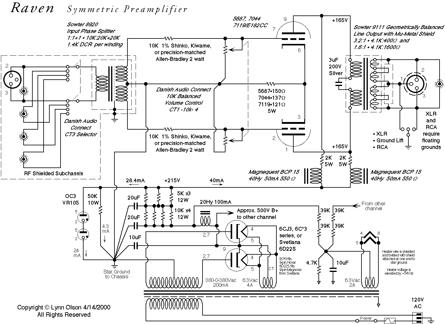
So back to the transformers.
These are the encapsulated ones which I attempted to use;
2x115V PCB Mounting Toroidal Power Transformers from Nuvotem Talema
They do not work at all. Response tails off starting at 8K. They bare just about functional as CTC's but I will be pulling mine from the input when I locate some open ones.
These are their standard range;
Nuvotem Talema Toroidal Power Transformers - Standard Open 2x115V Primary
I have had great success with these in just about every application in which I have tried them in - including power amp output stages.
The ones which I am using in this preamp are from a different source;
VTX-146-030-112 - MULTICOMP - TRANSFORMER, 30VA, 2X 12V | Farnell United Kingdom
These seem to work just fine.
In this application you want to use as small a transformer as possible - mine where 15VA. This should increase primary inductance. You can use anything from a 7V to a 24V secondary depending on your gain requirements. 12V gives you about unity gain.
You cannot really use these as 1+1:1 transformers, step down is essential to overcome the high capacitance losses. Depending on the circuit response will start to droop at between 20Khz and 40khz.
I have consistently found that in every single case I have found that the anodes need to be applied to the two center wires as shown on the winding diagram with the +B applied to the outer wires. This has a considerable effect on ringing and on low frequency extension. Get it wrong and the top end will be harsh and the bottom end distorted. Get it right and the signal will smoothly fall off with a very slight peak at about 60kHz.
Shoog
Shoog,
Wouldn´t use Wikipedia as a reference.......
OK, can agree there are two definitions of LTP. In the tube world LTP is referenced as an SE input phaseinverter. In the sand world it is defined otherwise. Search for tube+LTP and see what you find......
Call it what you want. Still it´s nothing but a suboptimal balanced amp to me. Can agree an unbypassed tailresistor below to be used though. I am glad to see that this is what you would use if current-balancing wasn´t an issue. The expression "medium LTP" is new to me and is nowhere defined but I understand what you mean. As long as you don´t have the CCS´s in place, as you at moment have perfect balance, you still would benefit by using only a 110ohm tail and no cap.
If a CCS tail betters the amps performance when feeding with a balanced signal that is not 100% balanced (CTC?) the effect can be called NFB") . Nothing wrong with that in small doses. Does it correct even or uneven harmonics? I guess it mostly affects even.
. Nothing wrong with that in small doses. Does it correct even or uneven harmonics? I guess it mostly affects even.
As I previosly mentioned you need to have two at least 470uF back to back caps if you want to remove the boost you now have. But there I think you agreed above.
Have you had a chance to see any current drift yet?
Wouldn´t use Wikipedia as a reference.......
OK, can agree there are two definitions of LTP. In the tube world LTP is referenced as an SE input phaseinverter. In the sand world it is defined otherwise. Search for tube+LTP and see what you find......
Call it what you want. Still it´s nothing but a suboptimal balanced amp to me. Can agree an unbypassed tailresistor below to be used though. I am glad to see that this is what you would use if current-balancing wasn´t an issue. The expression "medium LTP" is new to me and is nowhere defined but I understand what you mean. As long as you don´t have the CCS´s in place, as you at moment have perfect balance, you still would benefit by using only a 110ohm tail and no cap.
If a CCS tail betters the amps performance when feeding with a balanced signal that is not 100% balanced (CTC?) the effect can be called NFB
. Nothing wrong with that in small doses. Does it correct even or uneven harmonics? I guess it mostly affects even. As I previosly mentioned you need to have two at least 470uF back to back caps if you want to remove the boost you now have. But there I think you agreed above.
Have you had a chance to see any current drift yet?
Last edited:
Current balance seems to be stable and good at the moment. It would probably stay that way for years - but I suspect it would slowly creep in and degrade performance without been noticed. Ultimately I anticipate the 5697's working for 5yrs or more - and I don't want to be replacing them a moment sooner than absolutely necessary.
One of my cardinal principles is "No Adjustment - ever".
Shoog
One of my cardinal principles is "No Adjustment - ever".
Shoog
Hey,
I assume you have seen the older Raven schematic at Sowter. One could copy it straight off for a toroid. Instead of the chokes one should use CCS´s but one then need higher B+.
This is K&K /Davenports take on the subject, also ready for mains toroids:
I assume you have seen the older Raven schematic at Sowter. One could copy it straight off for a toroid. Instead of the chokes one should use CCS´s but one then need higher B+.
This is K&K /Davenports take on the subject, also ready for mains toroids:
An externally hosted image should be here but it was not working when we last tested it.
Last edited:
Why?
We are talking topology and there are still two CCS´s and a mains toroid needed, the only difference being a higher B+ and the CCS´s being above the OPT instead of below the tube. Haven´t thought of it before but couldn´t this solution give a better PSRR?
So don´t mind the chokes and components specified and don´t look at their use of an exotic, expensive cap. And don´t mind their LL input transformer.
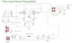
Here is the final version of the amp. Adding the current sink definately brought down the bass slightly - but increasing the size of the bypass is not having any significant effect.
Compared to my FVP5 it is a little bit more muted on the top end - but I am certain that changing out the encapsulated transformers in the front end will increase extension somewhat.
Shoog
Compared to my FVP5 it is a little bit more muted on the top end - but I am certain that changing out the encapsulated transformers in the front end will increase extension somewhat.
Shoog
Just what I said. You have CCS-action to the right tube but not to the left that will be 164ohm plus the dynamic impedance of the diode, maybe 10ohms. So your tail will be close to the left tubes 170-180ohm as the cathodes are signalwise together.
You probably use matched transistors but that was no problem to find, I guess.
And yes, I agree that is a weak tail. I´d call it strong but that is just me playing with words.
Thought you was going to do add another transistor in the left leg for CCS. That is what we used in the VETOR.
You probably use matched transistors but that was no problem to find, I guess.
And yes, I agree that is a weak tail. I´d call it strong but that is just me playing with words
.Thought you was going to do add another transistor in the left leg for CCS. That is what we used in the VETOR.
Realising that i had not fully understood the nature of the current mirror - I have just converted mine to a three transistor Wilson Current Mirror - thus stiffening the tail.
The result is very little different - but the bass is very extended and tight and overall there seems to have been a reduction in bloom and bloat from the original resistor tail.
Shoog
The result is very little different - but the bass is very extended and tight and overall there seems to have been a reduction in bloom and bloat from the original resistor tail.
Shoog
Extended listening after adding bigger caps and the extra transistor to the current mirror was showing a bit of stridency in the overall presentation. The detail was a bit to revealing. So I tried an old trick suggested by Allen Wright when using cap to cap bypassing, in the form of the 100R bleeder resistor.
The presentation has become a lot smoother now without losing any of the detail. I think this is settling into been a keeper for me.
Shoog
The presentation has become a lot smoother now without losing any of the detail. I think this is settling into been a keeper for me.
Shoog
Attachments
Hi Shoog,
If I remember your power amp correctly this is the same cathode coupling, yes? I have been trying to understand the cathode coupling capacitor values in the context of a preamp which presumably has a load of at least 100K rather than 8R speaker loading so the resistance seen at the cathode must be very high indeed(although just how high is the tail resistance) and thus your initial low value of cap. I suppose it must be fairly unusual to have AC coupling of cathodes in a preamp. Does anyone understand exactly what is going on here? Lars for example......?
If I remember your power amp correctly this is the same cathode coupling, yes? I have been trying to understand the cathode coupling capacitor values in the context of a preamp which presumably has a load of at least 100K rather than 8R speaker loading so the resistance seen at the cathode must be very high indeed(although just how high is the tail resistance) and thus your initial low value of cap. I suppose it must be fairly unusual to have AC coupling of cathodes in a preamp. Does anyone understand exactly what is going on here? Lars for example......?

whatever range of dynamic impedance you have between tubecathode and "ground" , what capacitor see is impedance between two cathodes ;
cathode node is pretty low impedance node , so - conclusion is - more capacitance , better (greater) AC coupling between them
as always , goal is to find what's enough , not using more than that ; think of speed , as illustration
cathode node is pretty low impedance node , so - conclusion is - more capacitance , better (greater) AC coupling between them
as always , goal is to find what's enough , not using more than that ; think of speed , as illustration
- Status
- This old topic is closed. If you want to reopen this topic, contact a moderator using the "Report Post" button.
- Home
- Amplifiers
- Tubes / Valves
- My poor man version of the Raven Preamplifier.