Pls see attached circuit - I'm planning a build but hoping to use the 6CG7 rather than the 6DJ8 (primarily because I have some 6CG7 tubes, but also because they seem to have a better reputation among audiophiles than the 6DJ8/ECC88).
Looking at the circuit, the 10K plate resistor might be a bit low for the 6CG7, probably 20-33K would be more linear? But using this value might see the plate voltage drop quite a lot due to R11 18K dropper.
The 18k dropper is probably needed to keep a low plate-voltage for a 6DJ8: +/- 100V, but from the datasheet the 6CG7 appears to be good for up to 300V. Would 5K as a dropper be enough to smoothen the B+?
Do we also need to increase R8?
Any suggestions re other changes most welcome.....
Attachments
R5/R10 should presumably be on the other side of the output capacitor C7/C8, so they act as an output ground reference.
The existing circuit has far too much gain for a line stage. 6CG7 would reduce the gain, but still rather high. A redesign would be needed to cope with the different valve characteristics. Reckon on changing every resistor value apart from R1,R2,R6,R7. C3 might need to be bigger too, as you might have worse PSRR with the 6CG7.
The existing circuit has far too much gain for a line stage. 6CG7 would reduce the gain, but still rather high. A redesign would be needed to cope with the different valve characteristics. Reckon on changing every resistor value apart from R1,R2,R6,R7. C3 might need to be bigger too, as you might have worse PSRR with the 6CG7.
R5/R10 are totally out of place here and will not do any good. Probably a drawing error. Remove or move them to the other side of the cap. They should also be made bigger try 3-500k. About the 6DJ8 circuit it is very illdesigned with badly chosen component and voltage values. But as you are redesigning for 6CG7, no problem with that. Note the 6CG7 has much higher Rp giving higher Zout, between 5-10k.
Eh? Are you talking about Miller effect - if so unlikely to be a major issue in either case. LF is determined by capacitors, not valves.
Ah no. The Rp of the 6cg7 is some three times higher than a 6dj8, not counting the plate resistor value. With X (both resistance and capacitive load), whatever the high frequency response is for the 6dj8, it will be reduced by some 3 times with a 6cg7. (Using very general figures.)
Yes, low frequency response is indeed limited by output coupling cap and somewhat by the cathode bypass cap (until say, Xc is some 10 times that of Rk). Sorry for the error.
In fact, we should also check for differences in the current feedback between tubes, as it will impact the bass as well.
As such the highs will be slightly reduced with the 6cg7 in the circuit provided. Bass will depend upon any change in Rk and Ck.
Cheers.
Last edited:
Ah no. The Rp of the 6cg7 is some three times higher than a 6dj8, not counting the plate resistor value. With X (both resistance and capacitive load), whatever the high frequency response is for the 6dj8, it will be reduced by some 3 times with a 6cg7. (Using very general figures.).
The output impedance of a CC stage is the tube Rp in parallel with the plate load (10K in this case). Even if the 6CG7 plate resistance is 3 times that of the 6DJ8 it will increase the output impedance by a smaller ratio. Rp for the 6CG7 is typically 10K giving an output impedance of about 5K. Even with 100pF capacitive load the -3dB point is over 300KHz.
Cheers
Ian
And the -1db point would be approximately 150khz, -.5db would be approximately 104khz. 20khz is -.02db. Doesn't seem like much except the response is added to all the other component's responses in the system. All stages and components make a difference in the highs and lows perceived.
I believe someone above mentioned using a 20k to 30k Rl instead of 10K, which would give more difference. But let's use your example, 5k vs the 6dj8 in parallel with 10k ohms RL. Ok, that comes to approximately 2.1k, so the 6cg7 has some 2.35 times the output Z of a 6dj8 using a 10K RL. However, a 6dj8 can use a much lower RL to increase its bandwidth, and increase the ratio..
Your figures are correct given the initial conditions of 10khz. For a 6dj8, we are talking 700khz. The rise time (attack time) difference will be noticeable according to an artlcle Jneutron mentioned some years ago.
Next consider the total capacitance load which includes not only the IC capacitance but amplifier input capacitance, which is considerable in tube equipment. I would say 300khz is probably on the high side. Remember each stage and component reduces the high frequency response.
All in all there will be a change in percepton.
Cheers.
Last edited:
Well spotted - I didn't notice the R5/R10 issue...I'll just replace R5/R10 with wire link, then solder resistors from signal wire to GND on the output side of capacitor....
What values shall we use for R3,R4,R5,R11,R12,C3?
after reinstalling R5/R10 right after the output coupling caps, you can just stick in the 6CG7 and have a listen, tell us what you hear.....

Very unlikely. Many sources will have come through a 20kHz brick wall filter. Moving your head a few mm in a typical room will cause a bigger change in HF frequency response. Straining at gnats!
Unfortunately not true. A 20khz bandwidth, so? The changes you mention involve several db peaks and valleys which are almost always less than 1/3 octave bandwidth. As such virtually not noticeable (unless a harmonic falls in said bandwidth) according to Rane.
An experiment to perform is to move one's head a few inches and notice very little if any difference.
However, even a small change in frequency response, over several decades bandwidth, and one will notice a difference.
All components have a bandwidth and so each is important to the total outcome.
Cheers and all the best.
Last edited:
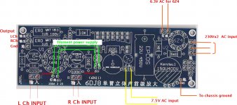
I've built the PCB for the 6DJ8 (see attached pcb picture) and it works fine. I can just snip out R5/R10 (sorry my initial idea to replace with a wire was ludicrous), then solder a new R5/R10 from tip to sleeve at the RCA output jack - this will be OK (I think).
Why is there conjecture about the ground reference resistor? I always thought any value > 100k would be okay?
Why is there conjecture about the ground reference resistor? I always thought any value > 100k would be okay?
Attachments
And the -1db point would be approximately 150khz, -.5db would be approximately 104khz. 20khz is -.02db. Doesn't seem like much except the response is added to all the other component's responses in the system. All stages and components make a difference in the highs and lows perceived.
Cheers.
You are correct, that all stages make a difference to the overall bandwidth. In this instance there are probably no more than three that the OP has any control over: the source, this pre amp and the power amp. The source is unlikely to have any significant content beyond 25KHz and the power amp (if tube based) would be lucky to be 3dB down at 60KHz. This pair contribute an order of magnitude more difference to the perceived bandwidth than does the preamp and hence changing its bandwidth from 300KHz to 700KHz would be completely inaudible. Indeed, any sensible engineer would first make steps to increase the bandwidth of the other two components and not nit pick about the one component of the system that is completely over specified.
Cheers
Ian
Why is there conjecture about the ground reference resistor? I always thought any value > 100k would be okay?
You are right. As I recall the conjecture was not so much about its value but how it is shown in your schematic. It needs to be connected from the signal output to ground not from the tube anode to ground.
Cheers
Ian
You are correct, that all stages make a difference to the overall bandwidth. In this instance there are probably no more than three that the OP has any control over: the source, this pre amp and the power amp. The source is unlikely to have any significant content beyond 25KHz and the power amp (if tube based) would be lucky to be 3dB down at 60KHz. This pair contribute an order of magnitude more difference to the perceived bandwidth than does the preamp and hence changing its bandwidth from 300KHz to 700KHz would be completely inaudible. Indeed, any sensible engineer would first make steps to increase the bandwidth of the other two components and not nit pick about the one component of the system that is completely over specified.
Cheers
Ian
"would be completely inaudible" is making an assumption which is not supported by science. Jneutron and I have both reported such. Remember that a change in rise time will change the sound, regardless of the other components. When the overall rise time changes, the sound changes.
Cheers.
Last edited:
- Status
- This old topic is closed. If you want to reopen this topic, contact a moderator using the "Report Post" button.
- Home
- Amplifiers
- Tubes / Valves
- Re-designing 6DJ8 circuit for the 6CG7