This amp is not meant to be the “ultimate” anything, just something I built for a friend with a unique set of design goals. If you are a tube “purist” who doesn’t like solid state mixed with their tubes, just walk away, this isn’t for you.
I have a friend who’s a history teacher and is a fan of the 1930s-1950s. He retired from his previous job last year and I promised him a tube amp as a gift. I finally found the time to complete it and figured I would share the build.
Design goals:
1. My friend currently teaches in Africa but will return to the US next year to finish his PHD. After that, he may end up teaching anywhere in the world. So this amp has to automatically account for whatever wall voltage is available. It also has to be able to survive “Africa Hot” with no air conditioning.
2. My friend isn’t an audiophile, he doesn’t even have a set of speakers I would consider acceptable. Audio fidelity doesn’t have to be great, but I’ll do the best with what I have. If he gets a decent set of speakers, they’ll probably be low sensitivity bookshelves so I’ll need more than flea power.
3. I already had a pair of Hammond 1615 5K ohm push-pull transformers. That determined the class of tubes I could use and let me use ultralinear for a good compromise of sound quality and power.
4. It has to be safely enclosed since he has small children who might poke fingers where they don’t belong. And it has to look good for WAF.
5. I wanted to try a few non-traditional things and see how well they work. Voltage amplification will be through tubes, but I’m not afraid to use solid state for voltage followers or in the power supply.
6. Tubes couldn’t be exotic or unobtainium in case they needed to be replaced. I settled on the 6P14P-EV for the power tubes and the 6N1P for a driver, easily and cheaply available on ebay. The 6P14P is equivalent to the EL84 so he can swap out tubes if something happens to them.
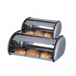
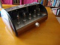
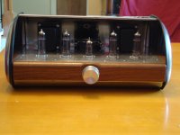
One of the first things that I needed was an enclosure. After looking around for a while, I found a stainless steel breadbox with an art deco / streamline look. From that I determined that I would have about 9” x 15” of horizontal space (about 7 x 13” after the supports are accounted for) and about 4” above and 2-3” below the main plate to work with. I removed the rotating lid and built side pieces out of wood and polyurethane resin to hold the main plate. 9” x 15” isn’t very much, so I needed to design as compactly as possible. I also knew that I would probably need to actively cool the amp, so I would need space for a fan somewhere.
The next design challenge was the power supply. The only way to get something auto-switching inexpensively was to use a switchmode PSU. Since the standard co-axial power jack is limited to 5 amps, I knew I would need at least 20 volts in order to safely get 100 watts of power (I wanted some overhead). I also realized that I would need to convert the DC into a high voltage B+. I found a 24v 5A LITEON switchmode PSU and a 200 watt, 24v to 220v inverter on e-Bay and figured I’d use those. Search ebay for “200W DC 24V to AC 220V Power Inverter” and “LITEON 24V 5A AC POWER ADAPTER” if you want to find the models I used. As a nice side benefit, the 24 volts would run the 6P14P heaters in series quite nicely. It could probably be done with a 12 volt PSU and inverter, but it might have required more current than the jack was rated for and I wanted to play it safe. I tapped B+ from the inverter after the rectifier and capacitor but before the modified sine wave generator. I was hoping for 300-320v DC but ended up with 260 volts. The frequency is quoted as “ultrasonic” and I heard no ringing from the inverter transformer, so noise from the B+ shouldn’t be an issue. As a precaution, an additional RC filter was used on the front end, but that was probably overkill.
I initially tried using a LM2595 DC-DC buck converter to get 6.3v for the 6N1P, but the inductor on it vibrated at several thousand hertz, giving off a high pitched whine and vibrating the leads to the 6N1P so badly that the tube itself became microphonic at several KHz. I ended up just tossing it and using four 8 ohm resistors in series to drop the voltage down. Not as efficient, but effective.
I have a friend who’s a history teacher and is a fan of the 1930s-1950s. He retired from his previous job last year and I promised him a tube amp as a gift. I finally found the time to complete it and figured I would share the build.
Design goals:
1. My friend currently teaches in Africa but will return to the US next year to finish his PHD. After that, he may end up teaching anywhere in the world. So this amp has to automatically account for whatever wall voltage is available. It also has to be able to survive “Africa Hot” with no air conditioning.
2. My friend isn’t an audiophile, he doesn’t even have a set of speakers I would consider acceptable. Audio fidelity doesn’t have to be great, but I’ll do the best with what I have. If he gets a decent set of speakers, they’ll probably be low sensitivity bookshelves so I’ll need more than flea power.
3. I already had a pair of Hammond 1615 5K ohm push-pull transformers. That determined the class of tubes I could use and let me use ultralinear for a good compromise of sound quality and power.
4. It has to be safely enclosed since he has small children who might poke fingers where they don’t belong. And it has to look good for WAF.
5. I wanted to try a few non-traditional things and see how well they work. Voltage amplification will be through tubes, but I’m not afraid to use solid state for voltage followers or in the power supply.
6. Tubes couldn’t be exotic or unobtainium in case they needed to be replaced. I settled on the 6P14P-EV for the power tubes and the 6N1P for a driver, easily and cheaply available on ebay. The 6P14P is equivalent to the EL84 so he can swap out tubes if something happens to them.
One of the first things that I needed was an enclosure. After looking around for a while, I found a stainless steel breadbox with an art deco / streamline look. From that I determined that I would have about 9” x 15” of horizontal space (about 7 x 13” after the supports are accounted for) and about 4” above and 2-3” below the main plate to work with. I removed the rotating lid and built side pieces out of wood and polyurethane resin to hold the main plate. 9” x 15” isn’t very much, so I needed to design as compactly as possible. I also knew that I would probably need to actively cool the amp, so I would need space for a fan somewhere.
The next design challenge was the power supply. The only way to get something auto-switching inexpensively was to use a switchmode PSU. Since the standard co-axial power jack is limited to 5 amps, I knew I would need at least 20 volts in order to safely get 100 watts of power (I wanted some overhead). I also realized that I would need to convert the DC into a high voltage B+. I found a 24v 5A LITEON switchmode PSU and a 200 watt, 24v to 220v inverter on e-Bay and figured I’d use those. Search ebay for “200W DC 24V to AC 220V Power Inverter” and “LITEON 24V 5A AC POWER ADAPTER” if you want to find the models I used. As a nice side benefit, the 24 volts would run the 6P14P heaters in series quite nicely. It could probably be done with a 12 volt PSU and inverter, but it might have required more current than the jack was rated for and I wanted to play it safe. I tapped B+ from the inverter after the rectifier and capacitor but before the modified sine wave generator. I was hoping for 300-320v DC but ended up with 260 volts. The frequency is quoted as “ultrasonic” and I heard no ringing from the inverter transformer, so noise from the B+ shouldn’t be an issue. As a precaution, an additional RC filter was used on the front end, but that was probably overkill.
I initially tried using a LM2595 DC-DC buck converter to get 6.3v for the 6N1P, but the inductor on it vibrated at several thousand hertz, giving off a high pitched whine and vibrating the leads to the 6N1P so badly that the tube itself became microphonic at several KHz. I ended up just tossing it and using four 8 ohm resistors in series to drop the voltage down. Not as efficient, but effective.
Attachments
Schematic
My first idea was to use the Simple EL84 design from diyparadisio.com, but I just didn’t feel comfortable with the design. So I borrowed from other people’s designs, notably SY’s red light district and some ideas from Tubelab. I went with a traditional driver/concertina/power tube configuration. The 6N1P uses a 2v LED for cathode bias and a 30K resistor on the anode, which should give gain near the tube Mu of 35. The output of the tube is a pair of 500K resistors as a voltage divider which feeds a MOSFET concertina. This then feeds the grids of the output tubes which are biased by a 6 x 6 array of 2v LEDs.
I laid out the physical design using Front Panel Designer software. I realized that six tubes might be too crowded, so I decided that I would use a LND150 MOSFET as a concertina phase splitter instead of a tube and save a socket.
Disadvatages:
1. Irritates the tube purists
2. Small signal MOSFETS are limited to about 2ma at typical tube voltages. Larger MOSFETS have larger gate capacitance. Not necessarily a problem, but small MOSFETS may not work well with difficult to drive power tubes and large MOSFETS may not work well with low current driver tubes
Advantages:
1. Irritates the tube purists
2. MOSFETS in follower configurations (which a concertina is) don’t amplify the voltage, so they impart no sonic signature
3. No problem with heater-cathode voltage exceeding spec and less current draw on the power supply since there is no heater
4. Reduced MOSFET internal resistance means both the source and drain (cathode and anode) have roughly the same source impedance, eliminating the one weakness of the concertina
5. The MOSFET costs less than a tube socket, never needs replacement, and is physically much smaller
I wanted to use a fan as an active cooling device. I chose a 12v 80mm Enermax Marathon fan because the magnetic bearings mean no bearing noise and 80mm fans can be found anywhere if it fails and needs replacement. I’ve used these extensively in computers and know that they have some air noise when run at 12v, but become inaudible at less than 10 volts. I also wanted a front mounted power switch for convenience. I like the new ALPS PCB mount potentiometers which have an integrated switch, so I used a 20K value of one of those for volume and power control. The switch isn’t rated for 24v and 5 amps, so I ran a 12v automotive relay and a dropping resistor in series with the fan and switch. Turning on the switch activates the fan and relay, which then powers up the entire system. If the fan fails, hopefully it will prevent the system from powering up and possibly overheating. In operation, with the dropping resistor and two small bypass resistors, the fan runs at 9v and is inaudible.
Attachments
Assembly
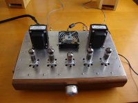
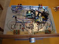
After playing with the position of everything for a few weeks, I printed out the Front Panel Designer layout. I bought a piece of 15 x 9” 6061 3mm aluminum from Online Metals and punched a whole lot of starter marks with a center punch, and went to town with the drill press and step drills. I made a front face from a piece of walnut left over from building my son’s crib. I used a 1” x 1” x 12” piece of aluminum L bracket to attach the power plug, RCA input jacks, and binding posts. Everything bolts directly to the main aluminum plate, which makes future removal and servicing much easier.
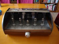
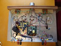
Assembly was fairly straightforward – tube sockets, transformers, and the fan were bolted onto the plate, as well as the L bracket and front face. Miscellaneous items were added, like a 3 terminal junction block which is great for star grounding. The inverter was attached on one side by a block of wood with a slot cut in it for the PCB board, and on the other side I flipped the primary side MOSFETs to the other side of the PCB and attached them directly to the main plate for heatsinking. Then everything was wired up according to the schematic in point to point fashion. It’s a bit messy, but it worked first time. I re-ran wires a few times to tweak a few things, but there were no major issues. The amp is completely without hum, even with two switchmode power supplies.
The sound? I’m not one to wax eloquent. I knew going in that the Hammond transformers would be the weak link. I had done a frequency response test using Rightmark Audio Analyzer on the transformers themselves and found noticeable roll-off on both the high and low ends. Two toroid power transformers that I tested were straight as rulers across the audio frequency band, so these are definitely limited in design. The sound is clean and neutral, and due to the ultralinear operation, kicks out a very usable amount of power. All in all, I’m very happy with how this project turned out.
After playing with the position of everything for a few weeks, I printed out the Front Panel Designer layout. I bought a piece of 15 x 9” 6061 3mm aluminum from Online Metals and punched a whole lot of starter marks with a center punch, and went to town with the drill press and step drills. I made a front face from a piece of walnut left over from building my son’s crib. I used a 1” x 1” x 12” piece of aluminum L bracket to attach the power plug, RCA input jacks, and binding posts. Everything bolts directly to the main aluminum plate, which makes future removal and servicing much easier.
Assembly was fairly straightforward – tube sockets, transformers, and the fan were bolted onto the plate, as well as the L bracket and front face. Miscellaneous items were added, like a 3 terminal junction block which is great for star grounding. The inverter was attached on one side by a block of wood with a slot cut in it for the PCB board, and on the other side I flipped the primary side MOSFETs to the other side of the PCB and attached them directly to the main plate for heatsinking. Then everything was wired up according to the schematic in point to point fashion. It’s a bit messy, but it worked first time. I re-ran wires a few times to tweak a few things, but there were no major issues. The amp is completely without hum, even with two switchmode power supplies.
The sound? I’m not one to wax eloquent. I knew going in that the Hammond transformers would be the weak link. I had done a frequency response test using Rightmark Audio Analyzer on the transformers themselves and found noticeable roll-off on both the high and low ends. Two toroid power transformers that I tested were straight as rulers across the audio frequency band, so these are definitely limited in design. The sound is clean and neutral, and due to the ultralinear operation, kicks out a very usable amount of power. All in all, I’m very happy with how this project turned out.
Attachments
Last edited:
After looking around for a while, I found a stainless steel breadbox with an art deco / streamline look.
Now, that's cool! Pretty darn creative. I'd scrap the fan if at all possible, though.
I initially tried using a LM2595 DC-DC buck converter to get 6.3v for the 6N1P, but the inductor on it vibrated at several thousand hertz
That's usually what happens when the inductor saturates. Did you verify that the saturation current for the inductor you chose was greater than the peak current in your circuit? If the inductor isn't designed for the peak current, it'll saturate, get cranky, and whine. It could also be caused by instability or a current limiter kicking in.
I've had very good experience with National/TI's recent crop of buck converters. LM2734, LMZ12xxx, and LM2267x to mention a few. See my website for actual circuits.
Anyway. Congrats on a project well done. I suggest that you post an image of the finished amp in the Images thread (near the top of the forum page).
~Tom
The fan is silent. You can't hear it if you put your head next to the tubes. It moves just enough air to keep everything much cooler. I pretty much wouldn't want to run a closed box in 100 degree Africa heat without some way to get rid of the heat, at least just to extend the life of the electrolytic caps.
The buck regulator I bought from an e-bay auction. The chosen components were probably designed for "average" conditions. The inductor was marked 470, which I assume is 470 mH. The datasheet recommends about half that for the operating conditions. I don't think I've got another lying around to swap out and test, so I'm just going with the passive solution for now. Maybe in another amp I'll try to get the buck regulator working right.
The buck regulator I bought from an e-bay auction. The chosen components were probably designed for "average" conditions. The inductor was marked 470, which I assume is 470 mH. The datasheet recommends about half that for the operating conditions. I don't think I've got another lying around to swap out and test, so I'm just going with the passive solution for now. Maybe in another amp I'll try to get the buck regulator working right.
The fan is silent. You can't hear it if you put your head next to the tubes. It moves just enough air to keep everything much cooler.
Sweet!
The buck regulator I bought from an e-bay auction. The chosen components were probably designed for "average" conditions. The inductor was marked 470, which I assume is 470 mH.
Arh... eBay "quality". That's probably it. 470 is probably 47 uH. 474 would be 470 mH - way big for a modern switcher.
Switchers are not that hard to deal with. But they are not as "plug&play" as linear regulators. They tend to be sensitive to component choices - not just the inductance and capacitance, but also to a much greater extent the parasitics of those components. The ESR of the output capacitor matters greatly for stability, for example. That's why I make very specific recommendations for my Universal Filament Regulator.
~Tom
I tried adding an additional 680uf OSCON cap to the output to try to lower the ESR, but to no effect. I've got a few through-hole inductors of various values I might try if I get the time - maybe just using a resistor dummy load since a tube filament is basically resistive in nature.
I tried adding an additional 680uf OSCON cap to the output to try to lower the ESR, but to no effect.
A lower ESR will lower the output voltage ripple, but may compromise stability. For stability you need the ESR to be within a certain range and the single-digit mOhm range of the OSCON's is not always the right answer. Run the simulation or experiment and measure the output impedance, transient response, or both to know for sure.
And changing the output cap does absolutely nothing if the root cause is that the inductor is undersized and, thus, saturating.
Go back to your drawing board for a few but necessary adjustments, though!
What do you have in mind? Just curious.
~Tom
Fullrangeman - Well, it is mostly hard wired, but if you think it was quick or easy to build...
revintage - I was planning on about 300 to 320v of B+ but ended up with 260, so my initial values might be a bit off. I'll have to take some measurements since tubes don't necessarily match their spec sheets either.
Tom - I figured I'd try the capacitor first since the output capacitor looked fairly generic, it only took a few seconds to solder on. Now I know better than to trust before testing.
Fenris, all my congrats for your design. I love it also because of the 1st Advantage/Disadvatage
FullRangeMan :Who would not ask a "dumb in electronics" person to wire an 6C33C socket, without setting the house on fire. Also "dumb in electronics" people go for the recognized valves....
FullRangeMan :Who would not ask a "dumb in electronics" person to wire an 6C33C socket, without setting the house on fire. Also "dumb in electronics" people go for the recognized valves....
I was eyeing up the LND150 for my next project for the same reasons, but wasn't sure how to implement it correctly eg bias.
I'm sure that this will rattle the purists.........In many guitar amp circuits, just stick it into the 12AX7 sockets.....it works.
I used one as the PI in the amp I made for the $100 amp challenge, the gate was tied through a stopper (4.7K) to the plate of the driving tube with equal value resistors for the plate and cathode set for about 1 to 2 mA of current.
Stuck a pair into the usual Marshall LTP PI too, they work. Also useful in many 12AX7 based cathode follower circuits.
A lower ESR will lower the output voltage ripple, but may compromise stability. For stability you need the ESR to be within a certain range
As Tom pointed out many voltage regulators including linear ones require some ESR in the output cap. A perfect cap introduces a zero in the feedback loop and can create instability or screw up transient response. In the tube amp world the regulator output often sees an inductive load, the OPT. The often used Maida regulator can react unpredictably to large transients through the OPT (kick drum stomp) when a big film cap (mutor run) is placed across its output. So will most switchers. Some linear regulators have a minimum ESR spec, some don't state it, but still need it since they were designed before low ESR caps were common. A few of the newer designs state that they are stable with any cap, or state that they work with ceramic output caps.
I used the NJR 317 in a mosfet Maida since it does not have an exposed metal tab. It is unstable into a motor run cap, while the old Motorola parts I have are OK. I'm guessing that the newer parts have more gain in the feedback circuit.
As Tom pointed out many voltage regulators including linear ones require some ESR in the output cap. A perfect cap introduces a zero in the feedback loop and can create instability or screw up transient response.
A while back I read about optimizing the LM317 for ESR here:
Using 3-pin regulators off-piste: part 1
a very interesting read.
- Status
- This old topic is closed. If you want to reopen this topic, contact a moderator using the "Report Post" button.
- Home
- Amplifiers
- Tubes / Valves
- Just what the world needs - another EL84 amp