I believe that there is some psychosis about it.
Yes, there is much of that. There are, however, some basic engineering issues in selecting components- for tube guys, Morgan Jones covers the stuff in gory detail in his book. Rule of thumb- components specifically marketed to audiophiles are almost invariably grossly marked up and no better than reputable industrial brands. Quite a few "audiophile" components are significantly inferior.
If you can't get a component from a mainstream supplier like Newark or Mouser or Digikey, that's a strong indication that you're paying for psychosis and prestige rather than performance. You don't find special audiophile grade resistors in a radio telescope, a CAT scanner, or a neutron detector.
SY: I agree. I have made tenths of electronic designs, from a simple audio amp to a solar cell battery charger regulator using two SMPS´s with current sharing and with both operating 180 deg out of phase (from who I´m powering my ham radio stuff including a packet radio modem and 12V low power fluorescent lamps), and I could never see differences so small. Yes, I can see the performance difference between, say, an audio 85deg cap in a SMPS, and a 105deg Nichicon, by example (measuring ESR, ESL, durability, etc.). But, I can´t understand which difference may be between a coupling cap of polyester, polypropylene, paper, oil, etc. in terms of "sound effects".
I'd recommend good 1% tolerance 1/2W (RN60) metal films like Dale or PRP (Precision Resistive Products), for the eq caps polystyrene film and foil caps like the REL RT series. For coupling and bypass capacitors Russian FT-3 series comes to mind. Output cap probably a good polypropylene like the Clarity SA/ESA series or something from Janszen.. There are many choices, these are just some that have worked for me in the past, none are too expensive.
Alternately you could order parts from Michael Percy, and have them shipped to Vietnam by mail.. I've bought small quantities of parts from him for more than 24yrs now - highly recommended. Here: Michael Percy Audio Ordering Information Not sure about duty and the like however.
Many thanks, Kevin. I will check it out.
BTW, can you please kindly tell me more about the pros and cons of moving R25 before R17?
Thanks and regards
Andersen
Many thanks, Kevin. I will check it out.
BTW, can you please kindly tell me more about the pros and cons of moving R25 before R17?
Thanks and regards
Andersen
No cons really except that the combination should not exceed the rated maximum grid circuit resistance for the tube used.
Inverse RIAA Filter
Hi All,
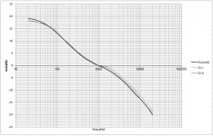
We speak of 1% components, calculations and simulations to meet the Goal of the RIAA curve.
How do we DIYers measure the results for accuracy? How do we know that all that precision did what we hoped?
Back in the early posts Revintage recommended the use of the Hagerman Technology LLC: iRIAA Filter for Phonostage DIY Kit "Inverse RIAA Filter" to test the results. Using this method the results depend on the design and accuracy of the inverse filter.
To use an "Inverse RIAA Filter" for testing my assumption is that all the items, Device Under Test and inverse filter all plug into a PC based software program for output of the results.
The question; do any of the DIY affordable PC programs have a RIAA curve built into them for testing?
DT
Hi All,
<snip>
To use an "Inverse RIAA Filter" for testing my assumption is that all the items, Device Under Test and inverse filter all plug into a PC based software program for output of the results.
The question; do any of the DIY affordable PC programs have a RIAA curve built into them for testing?
DT
As far as I know there aren't any affordable programs that have this feature, Audio Precision has provision for limit files that do this and can also do the inverse RIAA directly without an external network, but not what I would call affordable unfortunately.
I have two inverse networks, one used to be guaranteed +/-0.1dB (it's commercial and one of my former employers gave it to me when they stopped being interested in RIAA equalizers) - the other is home brew.
That said I usually do a response measurement and look at the overall response normalized to unity gain at 1kHz and compare a number of points on the curve with a set of tabular values. Works fairly well, but can be very tedious if you are looking at a lot of points.. The problem with the inverse network is that the response is the sum of both the errors in the inverse network and the pre-amplifier equalization, when you are getting into the 0.1dB range this is a huge problem.
I suspect that tenth dB accuracy (or at least verifying it) is going to be difficult to achieve in most PC based measurement setups, and no way to conveniently verify without precision external test equipment.
You can generate riaa wav test files with sox:
http://www.diyaudio.com/forums/analogue-source/203706-error-d-self-riaa-2.html#post2873134
http://www.diyaudio.com/forums/analogue-source/203706-error-d-self-riaa-2.html#post2873134
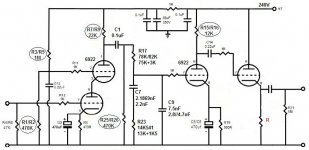
Based on the circuit in post 15 and a rough sim, I get R17=86k, R23=14.4k (12k+2.4k).
C1 is too small to feed an EQ so that should be 0.47u otherwise it may sound a bit bass shy; 1.5dB down @ 20Hz.
I like the coupling cap in the grid of the 2nd stage, then it can be 0.1u or smaller if the grid resistor is bigger than 470k. However that can make getting the EQ caps hard in 1% values. I like silver mica so not too hard to get 1% or better in high voltage types.
Also not sure if a 0.22u on the output is big enough. I'd use 0.47u to 1u. Depends what it's driving of course.
cheers,
Stephen
The calcs most people make a simplistic at best as they very rarely cover most of the variables even the most obvious ones.
Part of the calcs most people miss is the varying load of the EQ esp at low frequencies that will affect the low end and most people forget about the coupling cap effects esp at low frequencies plus the grid load effects of the 2nd stage.
Lipshitz while a great starting point misses out all these real world variables. Also look at the assumptions Lipshitz makes for the output Z of the driver and the load ratio of the load. Valve circuits almost never meet these assumptions.
Hence the reason I use a sim. Sim the cct, buy the 1% parts, stick them in and presto, done. Unless some gross errors have been made, that should be the end of it.
cheers,
Stephen
Cathode Follower
Hello again
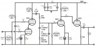
I intend to add a cathode follower stage at output as shown in the attached schematic. Can you please kindly advise me if it's ok and if C14 can be removed and what the value of R should be?
Many thanks and regards
Andersen
Hello again
I intend to add a cathode follower stage at output as shown in the attached schematic. Can you please kindly advise me if it's ok and if C14 can be removed and what the value of R should be?
Many thanks and regards
Andersen
Attachments
")
- Status
- This old topic is closed. If you want to reopen this topic, contact a moderator using the "Report Post" button.
- Home
- Amplifiers
- Tubes / Valves
- Need help on RIAA