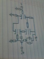
I can read it sideways, no problem - but the component ratios make a big difference (absolute values not necessary). For example, it looks a bit like a long-tailed-pair with a triode loading the second half, but depending on the values the first triode might be part of a LTP with gain, or a phase splitter with gain approximately 1. The RC network looks a bit like an Aikido noise reduction scheme, in the style of Broskie.The circuit seems to be on its side for me so very difficult to read, also I think the component values will be needed to work out what it does!
The two output valves appear to be opposing each other - count up the phase inversions from input to output via both paths. This is not single ended or push-pull - it is push-push.
Also, with no glass the vacuum may escape.
Whether it will work would depend on what it is intended to do. It will certainly consume electricity and heat a room.
Also, with no glass the vacuum may escape.
Whether it will work would depend on what it is intended to do. It will certainly consume electricity and heat a room.
Could be fixed up maybe. Take the resistor going to ground at the bottom and connect the grounded end to the cathode of the first stage, instead of to ground. Remove the wire from the 1st cathode to the 2nd cathode, connect the 2nd (bottom) cathode to ground thru a cap bypassed resistor for biasing. Make the plate resistor of the 1st (top) tube about Mu times (use Mu of 2nd tube, bottom) the cathode resistor to ground there, to proportion the grid drives. (Needs to take into account the V divider effect of the string of resistors at the bottom yet.) Presumeably an Aikdo like voltage divider at the bottom, will need adjusting to get the right hum cancelling on the bottom grid. Simulate, to see if this is all working correctly. (PSRR will likely depend on signal level without some further fixes.)
Put glass around the tubes before all the vacuum escapes.
Put glass around the tubes before all the vacuum escapes.
Last edited:
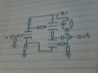
Looks like a Broskie CCDA with a bit of Aikido thrown in:
CCDA: constant-current-draw amplifier
It should provide some positive feedback and hence some additional second order distortion. I used a similar front end on a guitar amp I built except with a potentiometer in place of the first tube's cathode resistor. The wiper connected to the cathode of the second stage and allowed varying amounts of positive feedback. It makes a nice colored sound, but loses accuracy.
Except the "counter modulated" CCS is fighting the cathode follower here, instead of assisting it (check phase inversions as DF96 suggested).
Fenris's suggestion of the Broskie CCDA positive feedback may be what is intended here. Interesting, in that the added "CCS" tube on the bottom of the output follower puts the positive feedback thru a 1/Mu function (versus output V), so may largely remove the feedback loop distortion problem (Mu1 * 1/Mu2). Curious circuit. Doesn't correct the distortion of the input tube (to the output), but may prevent the positive feedback from making it worse.
Someone needs to rotate this image to prevent viewer headaches:
Attachments
Last edited:
- Status
- This old topic is closed. If you want to reopen this topic, contact a moderator using the "Report Post" button.
- Home
- Amplifiers
- Tubes / Valves
- circuit idea