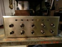
Not sure about how it works - it hasn't seen electricity in 3 decades!!, but it is in pristine! condition. It as in a console cabinet all its life and the daughter was selling off her dad's things. She could not remember ever hearing it work. Seems to have all/most of its original tubes AND some extras in boxes (may be just packrat jun??).
Anyway here are some pics of it out of the console.
I'm not sure if its possible, but would there be a way to get a pre-out from this and use it as a tube pre for my Citation II? My goal MIGHT be to bi-amp my Magie's with this and the Citation. May not need the horsepower but, I do want a tube Pre. Or I'll give it to my daughter to use for her Cornwalls.
For now, I need to get some ideas about how to power it after 3 decades! Any Scott experts out there? Especially if you're in the Chicago area.
Attachments
Oh my!!
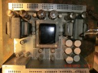
Before I bought it I opened the bottom - could not find anything visibly wrong, so was encouraged and bought it. But I just assumed the father stopped using because of an expensive failure.
The seller (daughter of the original owner) asked her dad for me if he remembered anything about why he stopped using it, In other words, give me clue what may have failed. She just got back to me.
He said it did not fail, he just stopped using it!!! No kidding. Sure 30 years means it will need some checking out and probably some parts, but at least it isn't a basket case!

Given that modern caps are so much smaller than they were 30 or 40 years ago, one trick sometimes used by restorers is to extract the contents from the old, dried up cans and then insert the new ones inside them, thus preserving the original appearance. Just be careful, since the insides are probably not that pleasant, chemically speaking.There is no room under to cram something and bypass the can caps, so i may be stuck replacing the cans. Can caps are so much more expensive!
I have one of these too, and the matching tuner. I traded a car for mine.....It was the first car that I ever owned too, a 1949 Plymouth.
The amp was sitting in a barn. The owner didn't remember when or where he got it. One of the 5U4's, one of the EL34's and both tall white ceramic resistors were physically broken where the tuner was sitting on top of the amp. After replacing those parts the amp worked. I used it daily for about 10 years, but I haven't turned it on in about 10 years. It was working when I put it in the closet.
Do you have a schematic? I have all the documentation including the service manual that came with mine. I can scan it if you need it.
These amps can sell for stupid amounts of money. It may be worth replacing the can caps correctly if you ever sell the amp.
Congrats, nice amp! Good to replace the caps as you probably know as you risk the transformers.
Maybe you can replace the can caps with the big JJ type or other quality tall caps and put clamps on them. You just don't want to drill any new holes. Make adapter plates with aluminum scrap if needed & Save the old can caps if you ever sell it.
I think Jim McShane of Jim McShane tubes could possibly make you up a kit of all needed caps if you ask him.
Easier than trying to restuff caps which some say isn't as good anyway (small mini caps don't work as well) and cheaper than buying replacement can caps. You can also increase the capacitance in the PS for a sonic improvement except right after the rectifier tubes.
Just a thought!
Randy
Last edited:
Just for an alternative viewpoint, I regularly see electrolytic cans more than 50 years old come back to life if brought up *very* slowly. I'll set aside several hours for the gig, hook a scope and a DC voltmeter to the first cap and temporarily replace the vacuum rectifier with a solid-state one (I keep one with octal socket just for the purpose). Bring it up on a metered variac very, very slowly, watching ripple and current draw constantly. Give it plenty of time and you may be pleasantly surprised, but rush it and you'll ruin the caps fersure. Several hours is not too long.
Modern high voltage caps in cans are often crap, so replacement isn't easy.
All good fortune,
Chris
ps: remove all the tubes first, of course
Modern high voltage caps in cans are often crap, so replacement isn't easy.
All good fortune,
Chris
ps: remove all the tubes first, of course
I agree Chris those early can caps can be really good in my experience . Maybe if watched carefully for heating up they may be okay for years. Maybe strap in a few extra big caps under chassis for improved sonics though!
I've read about a lot of new can caps failing too! Is it a self life problem?
Those white Ceracaps if used for coupling caps should be replaced as too big a risk from what I've gathered. Others almost as risky too!
Regards.
Randy
I've read about a lot of new can caps failing too! Is it a self life problem?
Those white Ceracaps if used for coupling caps should be replaced as too big a risk from what I've gathered. Others almost as risky too!
Regards.
Randy
Thanks Chris and Randy, and all ...
I've heard the same thing from a lot of folks. While others offer stern warnings.
I've never done as you describe on a tube amp, but I always restart SS gear on a dim bulb setup after a rebuild (maybe I shouldn't admit I have SS also on this forum??). But I'm pretty inexperienced with SS and even more with tubes. Tubes is a different animal - the parts are always older, and mistakes seem to be more expensive. (the Citation is my first attempt and Jim McShane is very helpful)
Anyway, when I got interested in tubes I got a variac, and of course I have a descent scope (in fact I have one fairly good dual trace tectronix and a couple primative ones and if it would benefit, I could use them to monitor more things) and of course multimeters.
So given its condition and I'd like to focus my meager budget on the Citation, I'd like to see if the Scott can be woken up as you describe.
If I understand correctly this can be done low risk if done carefully, so I'd like some help understanding exactly what I should do including some help knowing exactly on the schematic I'm hooking up, the steps (for example, start at what voltage, how big of steps, how long at each voltage) and exactly what components I'm monitoring).
Is it safe to assume if I pay careful attention, I will know if things aren't going well and can simply stop before I do any damage?
If someone is willing to offer that detailed of help, I would really appreciate it and have a schematic I can scan.
THANKS in advance!
BTW post #32 and 33 here Brought Home A H.H.Scott Stereomaster 272 integrated Amp!!! - Page 3 - AudioKarma.org Home Audio Stereo Discussion Forums has a pretty good scan of the Power Supply, if that will help ref where I am looking to monitor.
As Chris said :
1) take out tubes.
2) put SS diodes in place of tubes. Easiest to make out of old tube bases (you can buy new ones too) , or you can buy a plug in SS tube replacement subs. I think the commercial ones for sale are called copper caps. IN4007 or UF4007 or higher Amperage IN5408 or UF types wouldn't hurt either, diodes would be fine to make one, and you could even solder them in place under chassis temporarily. If you could find the right diameter of copper or brass brazing rod the same diameter of the tube pins you could do it up top . Polarity marked on diodes has to be right. Cover with plastic spray can caps etc. to protect yourself from shock.
3) hook up voltmeter as he said to measure voltage @ 1st cap along with scope if desired
4) you can use light bulbs in series with the variac too, (Bulb will glow brightly at first after turning up voltage a bit , but should dim if caps are reforming.)
The Dim-bulb Radio Tester
5) bring it up very very slowly. Take 12 hrs while monitoring (maybe overkill) Better longer though. Somewhere I read 24 + also hrs. Anyway it's better to go very slow if you have the time as you can't go back.
Feel can caps for any heating up. They shouldn't.
On a tube amp when your testing it with tubes in it always have a load on the speaker outputs. Either cheap speakers or large 25W 16 ohm resistors. You risk the output transformers if you don't.
Maybe someone also may have further or better instructions!
Replace coupling caps before using though once you find transformers are okay.
Randy
Last edited:
Hi Bigbargain. Both Chris and rmyauck are correct about these older electrolytic capacitors. I have personally powered-up 20 plus year dorment tube equipment many times with the procedure described below. I believe too many members here are too quick to recommend immediate replacement of otherwise still usable filter capacitors. You'll need a variac, voltmeter and a couple of SS diodes.
This is what I do. Remove all tubes for a test on a known good tube tester. With all tubes removed, temporarily replace the rectifier tube(s) with a pair of SS diodes (1A - 1KV) by either tack soldering them to the bottom of the tube socket, or by using a store-bought SS replacement rectifier. You can also make a replacement SS rectifier on an old tube base by soldering them in the pins. The reason for temporaily using SS diodes is because you don't want to try pulling current through under heated tube rectifier filaments.
Connect a voltmeter to the first electrolytic capacitor that's right off the rectifier. If you have a milliamp meter, break the connection from the original rectifier socket to the filter cap and substitute the milliamp meter. Plus to the socket, minus to the capacitor. About 100mA is typical in value. This milliamp meter is not totally necessary, but it's helpful to see what's going on.
With the amp connected to the variac, and turned on, slowly advance the variac voltage while watching the meters. Try to get up to 40 or 50 volts. The milliamp meter will go up, and then begin to fall back. You want to keep it as low as the capacitors will allow. If you don't use the milliamp meter, you must monitor the temperature of the capacitors by feel with your hand. If any becomes warm, reduce the voltage. Leave the low voltage applied for about an hour.
After this time, begin to increase slowly upward watching the meters and/or feeling the capacitor cans for temperature rise. How rapidly you can increase the voltage will depend on the condition of the caps themselves. As they reform themselves the current (and temperature) will stay low. Leave them run at 100 volts for another half hour. Keep doing this at 50 volt intervals until you can run them to near full voltage rating. This should take several hours. If it takes many many hours, the capacitors are in pretty poor shape and will need replacing. It's really a judgment call based on how well they reform. Time and current draw are your markers.
When you've gotten this far, it's time to put the tubes in and fire it up. Dummy load the speaker terminals, monitor the bias on the output tubes and follow the other's advice regarding the coupling capacitors.
Your amp uses two rectifiers. Determine if they are both in parallel or each on one side of the source. If in parallel, you only need to replace one tube with SS.
Last edited:
HolloState thanks for that!
Could he use light bulbs to get the same result as the milliamp meter in that the bulb should glow brightly when the variac is turned up then dim as the cap takes the voltage? Start with small wattage bulbs and increase as you turn up the voltage.
On post #14 schematic above it looks like parallel rect. tubes.
Regards ,
Randy
Last edited:
Nope, the filaments are in parallel, but not the tubes themselves. So a rectifier on each socket is needed. It's funny but I've read text on power supply design that says not to use rectifiers like that. If you need extra current capacity (but not in this case however) you should run the tubes in parallel. I think the reasoning is if one goes weak, the balance becomes offset to the load. Still, a lot of manufactures run them like the schematic, which I didn't see earlier.On post #14 schematic above it looks like parallel rect. tubes.
And yes, a lamp could be used as a current indicator in lieu of a milliamp meter. It's just a little more difficult to interpert then reading numbers, but still doable. And I don't think there's a need to increase wattage. It's current we're watching, which should be low. 25-40 watts is plenty. And the milliamp meter or lamp should connect to the filament center tap and the first capacitor.
Last edited:
I too have had very good luck reforming can caps and the advice you have received is all good. I do have one thing to add.
In many vintage amps the voltage ratings of the caps are often lower the farther you get from the rectifier as the resistors in the circuit drop voltage. Obviously, this voltage drop requires current and with all the tubes removed, there will be almost no current. My point is that all these caps will be at the same voltage during the reforming so you want to limit the reforming voltage to the rating of the lowest rated cap. Of course you can break the circuit up and reform them separately too.
This is all very obvious, but I wouldn't want you to destroy a good can.
- Status
- This old topic is closed. If you want to reopen this topic, contact a moderator using the "Report Post" button.
- Home
- Amplifiers
- Tubes / Valves
- Scored a very nice H H Scott 272!