I'm trying to figure out how to make tube preamp, with good quality, in low voltages, lets say 12VDC or +/-15VDC.
Some said that in that voltages, tubes will give huge distortion.
But I found 2 designs (available commercially) using this low voltages.
1. The tube is 12AU7. The voltage is 12VDC. The input signal is fed via 10k resistor to the cathode, 15k to ground (voltage divider). The grid is connected via 1k to ground, and the plate is connected via 100k to 12VDC. The output is taken from the plate to the next stage.
2. The tube is ECC88, the voltage is +/-15V. The signal is fed directly to grid, the plate is directly to +15V, the cathode is via 68K to -15V. The output is taken from the cathode to the next stage.
Those units are working fine, and I think gives good sound. I cannot hear the huge distortion that people mentioned (are they audible?)
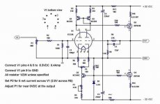
3. I also submit 1 design, quite low voltage. I havent tried it yet.
So there are 3 designs. Which one is the best according to you, elders? I'm not looking for designs that is excellent in lab figures, I'm looking for a design that is nice to listen to.
What do you think about these 3 designs? Are they give certain inferiorities compared to 250V designs?
Other question. Can I use 12AU7 in design no.2? Can I use +/15V in design no.3? I havent built anything yet.
Some said that in that voltages, tubes will give huge distortion.
But I found 2 designs (available commercially) using this low voltages.
1. The tube is 12AU7. The voltage is 12VDC. The input signal is fed via 10k resistor to the cathode, 15k to ground (voltage divider). The grid is connected via 1k to ground, and the plate is connected via 100k to 12VDC. The output is taken from the plate to the next stage.
2. The tube is ECC88, the voltage is +/-15V. The signal is fed directly to grid, the plate is directly to +15V, the cathode is via 68K to -15V. The output is taken from the cathode to the next stage.
Those units are working fine, and I think gives good sound. I cannot hear the huge distortion that people mentioned (are they audible?)
3. I also submit 1 design, quite low voltage. I havent tried it yet.
So there are 3 designs. Which one is the best according to you, elders? I'm not looking for designs that is excellent in lab figures, I'm looking for a design that is nice to listen to.
What do you think about these 3 designs? Are they give certain inferiorities compared to 250V designs?
Other question. Can I use 12AU7 in design no.2? Can I use +/15V in design no.3? I havent built anything yet.
Attachments
This circuit looks familiar. I think I've run across it on the web somewhere before.
I also vaguely recall that John Broskie (I may have misspelled his name, if so, I apologize) did an analysis of the circuit at www.tubecad.com. A wonderful site, by the way. Everyone, even solid state fans, should take a look at his site. At any rate, look through back issues of his webzine, looking for a letter from a reader about this circuit, or one similar.
In the meantime, my take is that this is one of those things that, while it can be done, you have to ask whether it should be done. There's little or no benefit to be had in treating a tube as though it were a transistor or vice versa.
The operating point for a tube is so constrained at low voltages that it's going to take a zillion dB of feedback to get anything like a decent waveform out of the circuit. Even a relatively high gain tube like the 12AX7 (mu=100...quoting from memory, so don't take that number as gospel) will not give you enough gain to do a good job when operated like that. Besides, why design a tube circuit, only to turn around and run it with gobs of feedback? Ugh. So you're left between a rock and a hard place. If you choose to run a tube at low plate voltages you're going to have horrendously high distortion figures--it'll be a sort of harmonic generator. The only way out of it is to run more feedback than the law allows, which will also ruin the sound, though in a different way. The circuit is not exactly what you'd call a good ambassador for tubes, which are capable of some of the most transcendent sound available in the realm of reproduced music.
Given the rail voltages in the circuit, I'd suggest using something like a pair of MPSA18's (a nice, low-noise bipolar transistor) instead of the tube. Maybe MPSA42's. Otherwise, I'd pass on it.
Grey
Hi,
Naturally I'd agree, for all general audio purposes please do use tubes what they were designed for.
That usually means high B+, the higher B+ the more dynamic range you can expect as you'll need to use high value plate resistors.
It's a blanket statement, I know...logic just the same.
Still, there are at least a dozen tubes that were designed to operate at very low plate voltage.
Most of them for car radios or computor service, neither of which demand high voltage swings.
Another derived application is MC headamps where the venerable ECC88/6DJ8 family can be made to work as a I/V convertor.
Thanks to its high transconductance and low noise this works well enough at voltages as low as 24VDC.
And it still very much a tricky odd-ball application.
Curves can tell a lot on this....look at Vg=0.
The ECC86 is another one but is reported to sound only so-so again a look at the plotted curves reveals why.
You could actually put the ECC86 to service, just don't expect great sounding results...I'd rather build a little tuner with that one.
Grey,
Feedback isn't going to do much good here either, you're just stuck with the inabilaty of the tube to work at such low voltages.
Depending on what transistor I can think of a few that definetely do sound better at higher voltages....In fact the best MOSsies I know of are often run at high B+.
There's no secret about it, if you want good dynamics highish voltage delivers the goods.
I guess people do get mislead when they see a buffer (CF to you and me) running from a bipolar supply rated at +/- 35VDC.
Guess we can't expect them to realise that to the tube this actually means a genderless 70VDC to work with.
Cheers,
Naturally I'd agree, for all general audio purposes please do use tubes what they were designed for.
That usually means high B+, the higher B+ the more dynamic range you can expect as you'll need to use high value plate resistors.
It's a blanket statement, I know...logic just the same.
Still, there are at least a dozen tubes that were designed to operate at very low plate voltage.
Most of them for car radios or computor service, neither of which demand high voltage swings.
Another derived application is MC headamps where the venerable ECC88/6DJ8 family can be made to work as a I/V convertor.
Thanks to its high transconductance and low noise this works well enough at voltages as low as 24VDC.
And it still very much a tricky odd-ball application.
Curves can tell a lot on this....look at Vg=0.
The ECC86 is another one but is reported to sound only so-so again a look at the plotted curves reveals why.
You could actually put the ECC86 to service, just don't expect great sounding results...I'd rather build a little tuner with that one.
Grey,
Feedback isn't going to do much good here either, you're just stuck with the inabilaty of the tube to work at such low voltages.
There's little or no benefit to be had in treating a tube as though it were a transistor or vice versa.
Depending on what transistor I can think of a few that definetely do sound better at higher voltages....In fact the best MOSsies I know of are often run at high B+.
There's no secret about it, if you want good dynamics highish voltage delivers the goods.
I guess people do get mislead when they see a buffer (CF to you and me) running from a bipolar supply rated at +/- 35VDC.
Guess we can't expect them to realise that to the tube this actually means a genderless 70VDC to work with.
Cheers,
> Some said that in that voltages, tubes will give huge distortion.
No. Tubes are linear down to very low voltages.
BUT: the clean output level of a tube is a small portion of the supply voltage. When you get to very small supplies, you have very-very small clean output. What they may mean: at 12V supply, a tube won't make the usual 1 or 2 volt signals used in hi-fi preamps.
Let us see. A useful rule of thumb is that a basic tube voltage amplifier can make a peak "undistorted" audio voltage of about 20% of the supply voltage. With a 300V supply, you can make about 60 volts peak audio (about 40 volts RMS audio). If you use a 12V supply, you can make about 12V*20%= 2.4V peak or 1.7V RMS audio. This is so close to normal 1V-2V audio levels that you have to get the bias exactly right, or it will clip horribly. (And once it starts clipping, even huge amounts of feedback are not going to make it clean.)
At that 20% of supply-voltage audio level, distortion tends to be about 5%. Some folks would call this excessive. To get down to 1% THD, we might have to reduce the signal level to 5% of the supply voltage. So for "low THD", a tube working on 12V supply might make only 0.6V peak, less than a half volt RMS, which is way too low for most audio line levels.
Also: when you work a tube at 300V, you do not have to be TOO careful about bias. If perfectly biased, you get about 60V at 5%THD, about 15V peak at 1%THD. if you only need a volt or two, you can "miss" the "perfect bias" and still get a nice couple-volt output. But at low voltage, you have to bias very carefully. Since tube data sheets don't show low-volt operation clearly, and tubes were not tested for low-volt uniformity, this really means experimentation and possibly individual adjustment.
> The tube is 12AU7. The voltage is 12VDC. The input signal is fed via 10k resistor to the cathode, 15k to ground (voltage divider). The grid is connected via 1k to ground, and the plate is connected via 100k to 12VDC. The output is taken from the plate to the next stage.
An interesting design. The cathode-input is unusual, "low" impedance (about 10,500Ω) by hi-fi standards. Linearity may be very-very good, because the input network forces current to be linear. Gain may be a little low, I'm not sure why it uses 12AU7. Output impedance is VERY high, being (((10K||15K)+500)*20)||100K= 130K||100K= 56KΩ (we usually aim for under 10K). In some systems it will work, in other systems it will be unable to drive the next input well. It is clean but low on gain. (In fact it may not have any power gain at all. I suspect it could be replaced with a passive transformer.)
> The tube is ECC88, the voltage is +/-15V. The signal is fed directly to grid, the plate is directly to +15V, the cathode is via 68K to -15V. The output is taken from the cathode to the next stage.
This is a simple cathode follower. 100% feedback, unity voltage gain. In many cases we do want voltage gain, and so this is unsuitable. In other cases we don't need voltage gain but do need to interface a high-impedance source (a volume pot, or that #1 amp) into a lower impedance (such as a power amp, or a tape output). With the components listed, it can put about 2 volts peak into a 10K load, a usable hi-fi level. Note that this one actually needs a full 30 volts of supply, even though it takes that as two 15V supplies. Back in the old days we often ran tubes on 45V batteries, so this is not much lower.
Note that both #1 and #2 use topologies not normally used (or used alone) in hi-fi. #1, the cathode-input stage, is very linear but has very unusual input and output impedances. #2, the cathode follower, is often used to buffer a voltage gain stage, but rarely alone. Both are highly linear, which means they don't have "that Tube Sound". And if they don't sound like tubes, why bother with tubes?
> lumanauw has attached this image:
Tubes are working at nearly 35V. The plate swing needed to drive Q5 may be less than one volt (depends a lot on the FETs and the load). The two tubes work as push-pull through the Q1 Q2 current mirror, doubling the output. At 35V supply, I would call this "borderline" between high-volt and low-volt operation. I would expect it to have some "Tube Sound", however the MOSFET Gate characteristics will add distortion and roll-off the treble feedback so it won't sound quite like any other tube amp.
> use a "space charge".. tube.
Not if you want hi-fi. Those tubes were very nasty. Their only reason for existing was to build car radios without any high voltage, in the 5 years that you could get a good powerful audio output transistor but not a good audio driver or RF transistor. Distortion was quite high, and you could tell even on AM radio. If you are thinking "portable": aside from heater power, the space-charge tubes "wasted" about 90% of their plate supply current to "suck" electrons off the cathode.
Thanks Mr. PRR for such a detailed answer about my original questions. Maybe some people like pictures better, so they do not pay attention to the design #1 and #2 (as I only described on words), and only focus on #3, as it has picture.
For your knowledge, I'm not familiar with tube designs. I actually dont know exactly how tubes works. My background in audio electronics is Transistor based.
The argument that you say is very intersting to me. If I'm catching you right, tubes can work to low voltages (12VDC) in clean distortion, only we dont have enough swing. Is this true? Why some people told me that in such low voltages,the distortion will be huge? I've tested the commercial unit with design of #1 and #2, and I dont hear excessive noise, hiss, distortion (that is why in my first post, I asked wheter this "excessive distortion" is audible or not? Because I dont hear it in the existing unit.
So your explenation make the most sense to me.
The reason why I want to built tube based preamp (or have tube in its path), is to get the "tube sound". I also not sure is the term "tube sound" is the same for you and me. For me the designs #1 and #2 have already gives the "tube sound", which is warm, and nice to listen to in a long time of listening to music. Transistors cannot do this. But from your answers, you said that in such voltages, I wont have that "tube sound". So is it the same "tube sound" that we are talking about?
You are right. #1 and #2 designs are not intended to have voltage gain on it. The complete design has other device before and after them that works the voltage gain. So I agree with you that those designs are only "passed thru" to give the "tube sound?"
Mr. PRR, what gives the "hiss" sound in tube designs? I compare tube based preamps and transistor or op-amp based, it is always the tube has more "hiss" sound (when I "pause" the cd player).
Since I'm going to built design #1 or #2, please tell me wheter the "hiss" sound will be the same, or louder than if I used the same design in high voltage (let say 250VDC compared to 12VDC or +/-15VDC, will the "hiss" figures are the same or not).
I asked this questions, because most tubes that I can buy here is double triode (ECC88, 12AU7, 12AX7, 12AT7).
I planned on this design (again sorry, I describe in words, not pictures):
-The input from the cd player is DC coupled - fed into [design#1 or #2], the output is fed via 470nF+47k into voltage gain opamp.
-The output of this voltage gain opamp is fed into the second [design#1 or #2]-dc coupled.
-The output of the second [design#1 or #2] is fed via another 470nF+47k into an opamp buffer, then it is the output (maybe via 100ohm resistor).
So there will be 2 tube buffer (I make use of double triode for 1 ch), and 2 opamps (1 for voltage gain and 1 for buffer).
Mr. PRR, what do you think of my design above? Will it give the tube sound that I like? If I built it without tubes, I only make an ordinary op-amp based preamp, without tube sound.
Since I will use 2 of the buffers, will the hiss sound be excessive? If you say it will be excessive I will only use 1 tube buffer (I will design only 1 tube for stereo). But if you say the hiss sound wont be a problem using 2 tube buffers, I will make the pcb 1 double triode for 1 ch (2 tubes for stereo)
But back to your experties. Which tube buffer will be the most suitable for the planning that I tell you? Will it be #1 or #2 design. Please tell me how do you choice between #1 and #2 for the planning that I make above.
When I hear the units available, I somehow hear the #1 sounds a little nicer than #2. But I maybe bias here, and moreover maybe the nicer design is not suitalble to my plan-design. So please comment on this, Mr. PRR.
Any news on this? How has this design turned out? I'm actually interested in this as an application of a low voltage design for for an all tube, battery operated guitar amp. Distortion wouldn't be a problem, in fact it would be welcome. I know of some designs that work well, but they use NOS space-charge tubes. (like the 12U7, 12K5, and 12AL8) I would like to come up with something that uses a current production tube, like the 12AU7. I know VOX has been marketing their "Cooltron" preamp pedals, that use a 12AU7 running off of 4 AA batteries, but the circuitry is pretty hush-hush (16 hour battery-life is claimed).
I've seen the 12AU7 used in both pre-amp and power-amp stages, but run in 'starvation mode', I've only seen pre-amp examples. The thing is, I'm baffled as to how bias is achieved (or calculated) at such a low voltage. There's something I'm just not getting. I'm wondering if a small, battery operated amplifier (Class A?) could be built, running the entire thing with a couple of 12AU7s in starvation mode? Still a newb when it comes to tubes, so please excuse my ignorance.
I've seen the 12AU7 used in both pre-amp and power-amp stages, but run in 'starvation mode', I've only seen pre-amp examples. The thing is, I'm baffled as to how bias is achieved (or calculated) at such a low voltage. There's something I'm just not getting. I'm wondering if a small, battery operated amplifier (Class A?) could be built, running the entire thing with a couple of 12AU7s in starvation mode? Still a newb when it comes to tubes, so please excuse my ignorance.
that use a 12AU7 running off of 4 AA batteries, but the circuitry is pretty hush-hush (16 hour battery-life is claimed).
I'll bet the batteries are in series, they are running the filaments strait off the batteries (4 x 1.5V = 6V) and I'd be willing to bet they are using a step up dc-dc converter of some kind to supply the plate voltage.
- Status
- This old topic is closed. If you want to reopen this topic, contact a moderator using the "Report Post" button.
- Home
- Amplifiers
- Tubes / Valves
- Very Low Voltage Preamp