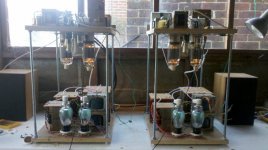
I have a problem with oscillation/parasitic in the driver of my E-Linear 813 PP amps here on this link Izzy Wizzy Audio
When one of the amps is going, I hear no oscillation and think everything is fine. Turn the second one on and then they both whistle; heterodyning would be the best word I can think of to describe it. I can reduce it to very small levels but not eliminate it. At one point I thought it gone altogether only to notice the amp ran super hot and then I found the output stage was well over biased - oops.
Some of the circuit has been altered from that shown in trying to find ways to stop it. There's no adjustable bias on the 813 grids. They are tied to ground now. The resistor divider to provide the ref for the upper grid on the cascode is now derived from a 0D3 as I had read a low Z supply can help. The grid is fed from about 470R followed by 0.01u to ground. Maybe not so low Z that way. I suppose I could get rid of the decoupling?
The heater supplies are now separate and the top is referenced here to the 0D3 now and the bottom section to ground.
All the grids have carbon 330R stoppers. I've tried a resistor instead of the CCS in the cathodes. I have an input transformer instead of the resistors.
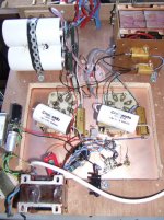
The anode load resistors are 50W wire wounds, the gold encased things. Could that be it? Would the slight inductance in them cause an issue? Earthing their cases changes things for the better but no fix.
I've used the screens in the valves and tied them to ground and the upper reference.
It is built on wood and all the wiring I think short and local to where it needs be. The pic on the site isn't the current layout. I realise cascodes are good at RF but I also know people use the diff cascode/hedge successfully. Maybe it needs better shielding and so should be built on say a PCB sheet, still point to point.
Any ideas welcome.
cheers,
Stephen
When one of the amps is going, I hear no oscillation and think everything is fine. Turn the second one on and then they both whistle; heterodyning would be the best word I can think of to describe it. I can reduce it to very small levels but not eliminate it. At one point I thought it gone altogether only to notice the amp ran super hot and then I found the output stage was well over biased - oops.
Some of the circuit has been altered from that shown in trying to find ways to stop it. There's no adjustable bias on the 813 grids. They are tied to ground now. The resistor divider to provide the ref for the upper grid on the cascode is now derived from a 0D3 as I had read a low Z supply can help. The grid is fed from about 470R followed by 0.01u to ground. Maybe not so low Z that way. I suppose I could get rid of the decoupling?
The heater supplies are now separate and the top is referenced here to the 0D3 now and the bottom section to ground.
All the grids have carbon 330R stoppers. I've tried a resistor instead of the CCS in the cathodes. I have an input transformer instead of the resistors.
The anode load resistors are 50W wire wounds, the gold encased things. Could that be it? Would the slight inductance in them cause an issue? Earthing their cases changes things for the better but no fix.
I've used the screens in the valves and tied them to ground and the upper reference.
It is built on wood and all the wiring I think short and local to where it needs be. The pic on the site isn't the current layout. I realise cascodes are good at RF but I also know people use the diff cascode/hedge successfully. Maybe it needs better shielding and so should be built on say a PCB sheet, still point to point.
Any ideas welcome.
cheers,
Stephen
UL outputs can oscillate. Two similar UL outputs might oscillate at similar frequencies, and so you hear the heterodyne. Adding snubbers between g2 and anode on each output valve is the usual cure.
IIRC the 813 makes a useful radio transmitter so you have to build to RF standards if you want it stable.
IIRC the 813 makes a useful radio transmitter so you have to build to RF standards if you want it stable.
A snubber is C and R in series. One end to anode, the other to g2. Typical values are a few k and around a nF. The idea is that it damps HF resonances in the OPT.
It might help if you can find what frequency the oscillation is at. It could be anywhere between 10's of kHz and UHF.
It might help if you can find what frequency the oscillation is at. It could be anywhere between 10's of kHz and UHF.
Thanks for that. Something else to look at. I also found this in a list of valves for UL service.
"813 1100V G2 (This tube is an excellent option for serious audiophiles but has a top cap and requires a centre-tapped 10 V AC/DC filament supply - 5A per tube. External wiring must be screened to prevent RF induction and parasitic oscillations. Adequate ventilation is essential) "
I will have to look at this a lot closer in the layout around the 813s2 especially the link to the top cap which apparently is a weakness for UL operation.
cheers,
Stephen
I would not try to build an RF PA on a wood base. Yes, you think it is an audio PA but the valves don't know that. With this sort of valve you must maintain a short low inductance connection between anode and cathode circuits, preferably with some RF loss, so it can't see a high-Q resonator to set oscillating. You may need to investigate valve RF PA anti-parasitic devices, such as deliberately lossy inductances in the anode circuit.
Also you can try some ferrite beads in the anode wire, and a resistor shunting them. It is usual for who used some of these tubes, in the 80 and 40 mts ham band, to use a small coil of 10-15 turns of 1mm diameter over a 47 to 100R 2W resistor, and then connect the coil to the resistor. In this way, it acts as a overloaded tank (resonant circuit) with parasitic capacitances and then oscillations are completely stopped. I haven´t experience if this trick can be a solution for your audio amp.
Good luck.
Good luck.
Got the amp working thanks to the suggestions here. Initially tried bigger grid stoppers, small coils over resistors on the plates and so on. Nothing worked. Then rebuilt just the finals stage. Still buzzed and hummed which I took to be a parasitic pointing to the UL stage as suggested here.
So went and rebuilt it in my usual fashion; how I would build phono stages. PCB ground plane, everything mounted on that, earthed. Short fat PCB 0V strip glued to it and earthed at one point to ground plane. All OP Tx wiring shortened and made as direct as possible and layout changed to be as short and direct as possible.
And they both work. Very quiet too. Yet to play it on the inside system; only in the shed at present but I like what I hear.
Thanks for the pointers. It helped to focus on what was needed to get it going properly.
cheers,
Stephen
- Status
- This old topic is closed. If you want to reopen this topic, contact a moderator using the "Report Post" button.
- Home
- Amplifiers
- Tubes / Valves
- Cascode Driver Oscillation