Hey there,
I was thinking of going for a basic CCS cathode bias on a 12au7 output, 22k-8 ohm output transformer, cathodes tied, but to be honest, I'm not sure where to start, or even if its a good idea. Ideally, I want to get the most power i can out of it at fairly low distortion.
First off, what transistor should i use? or MOSFET? What should it be rated for?
Secondly, I saw somewhere that a CCS won't allow class AB operation, would this set-up in class A give enough clean headroom?
Thanks for any help
Ricky
Sounds interesting, what speakers are you using? Also you say cathodes tied together. For single ended fine but if its push pull I reckon a seperate CCS per triode is best with a cap between the cathodes.
I have been thinking about a tiny amp for some nice full rangers I have so I hope some of the more knowledgeable folk pick this thread up.
Cheers Matt.
I have been thinking about a tiny amp for some nice full rangers I have so I hope some of the more knowledgeable folk pick this thread up.
Cheers Matt.
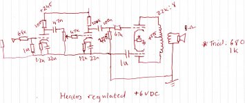
The speakers are nothing speacial, fairly old 8 ohm. This is just for my workbench during the late nights ") but i seem to have a fair amount of distortion in the output, but the preamp is clean, just a standard 12ax7 pair with volume in the middle. a CCS came to mind, but i wouldnt know where to start, and if bias could be adjustable to find a sweet spot, that would be helpful too.
but i seem to have a fair amount of distortion in the output, but the preamp is clean, just a standard 12ax7 pair with volume in the middle. a CCS came to mind, but i wouldnt know where to start, and if bias could be adjustable to find a sweet spot, that would be helpful too.
but i seem to have a fair amount of distortion in the output, but the preamp is clean, just a standard 12ax7 pair with volume in the middle. a CCS came to mind, but i wouldnt know where to start, and if bias could be adjustable to find a sweet spot, that would be helpful too.I have been using the good old 10M45 for CCS in my stuff so far. You can get really fancy with these depletion mode FETs but to be honest they work well enough on their own.
Could you post a circuit diagram of your amp. Don't worry about software, just scribble it down and take a photo.
Could you post a circuit diagram of your amp. Don't worry about software, just scribble it down and take a photo.
Last edited:
The problem is that all devices have significant second-order distortion. In a p-p stage these cancel in the OPT (current difference), but not in total device current (current sum). Second-order generates not only second harmonic but also DC. The net result, for fixed voltage bias, is an increase in average current - relatively harmless (quiescent current remains unchanged). For fixed average current set by a CCS, you get an effective biassing back to lower quiescent current - this might increase distortion. Normal cathode resistor bias is a compromise between these two extremes of fixed voltage and fixed average current - you get a somewhat larger average current and a somewhat smaller quiescent current. You would need to set the CCS for a higher current than would be optimum for small signals, so that there is 'room' to bias back for big signals. In this respect CCS bias is worse than normal cathode resistor bias.
This issue does not arise for a small signal LTP stage because there is very little second-order so very little DC shift.
This issue does not arise for a small signal LTP stage because there is very little second-order so very little DC shift.
The problem is that all devices have significant second-order distortion. In a p-p stage these cancel in the OPT (current difference), but not in total device current (current sum). Second-order generates not only second harmonic but also DC. The net result, for fixed voltage bias, is an increase in average current - relatively harmless (quiescent current remains unchanged). For fixed average current set by a CCS, you get an effective biassing back to lower quiescent current - this might increase distortion. Normal cathode resistor bias is a compromise between these two extremes of fixed voltage and fixed average current - you get a somewhat larger average current and a somewhat smaller quiescent current. You would need to set the CCS for a higher current than would be optimum for small signals, so that there is 'room' to bias back for big signals. In this respect CCS bias is worse than normal cathode resistor bias.
This issue does not arise for a small signal LTP stage because there is very little second-order so very little DC shift.
Hi, I have to admit I might not have fully understood this issue. When you say average current, do you mean the sum of the 2 sets of currents flowing thru the 2 cathodes towards ground?
Yes. Under zero-signal conditions the quiescent current (set by the bias) is obviously equal to the average current. When a signal is applied second-order distortion causes the average current and quiescent current to part company. In pure Class A the difference could be 10%; for AB it could be 20-30%. Whether average goes up, or quiescent goes down, depends on the bias arrangements.
The DC comes from trigonometry. Multiply two identical sine waves together (which is what second-order distortion does) and you get two outputs: a sine at twice the frequency, and a DC level. These two outputs are at the same amplitude - DC = peak sine. You won't see the second harmonic coming out of the OPT because of cancellation, so people often forget how much is actually generated in each output device, but the DC affects the bias.
The DC comes from trigonometry. Multiply two identical sine waves together (which is what second-order distortion does) and you get two outputs: a sine at twice the frequency, and a DC level. These two outputs are at the same amplitude - DC = peak sine. You won't see the second harmonic coming out of the OPT because of cancellation, so people often forget how much is actually generated in each output device, but the DC affects the bias.
Yes. Under zero-signal conditions the quiescent current (set by the bias) is obviously equal to the average current. When a signal is applied second-order distortion causes the average current and quiescent current to part company. In pure Class A the difference could be 10%; for AB it could be 20-30%. Whether average goes up, or quiescent goes down, depends on the bias arrangements.
The DC comes from trigonometry. Multiply two identical sine waves together (which is what second-order distortion does) and you get two outputs: a sine at twice the frequency, and a DC level. These two outputs are at the same amplitude - DC = peak sine. You won't see the second harmonic coming out of the OPT because of cancellation, so people often forget how much is actually generated in each output device, but the DC affects the bias.
If I understand you right, when a pp pair get a signal, the current changes around a point Different from the Q point, due to the DC level generated together with the 2nd harmonics. The current will actually changes round a point which you call Average current point, and will be higher than the Q point.
OK, let's see a special case.
Assume we bias the output tubes with a CCS at their cathodes. Also, the grid voltage is setup in a fixed bias mode using a resistor network. The CCS will force the combined current thru the tubes to remain constant, so the tubes has to still change their current around the Q point somehow. Then the grid voltages care less what's going on in the tubes but are determined by the fixed bias setup modulated by the input signals. Hence in order to fulfill the extra DC level due to 2nd harmonics, the only thing I can think of is that the tube will flow a different plate voltage change pattern, or in other words the load line is affected and distorted. Will it sound worse?
You can't combine CCS bias and fixed voltage bias. All you get is CCS bias, with the grid and cathode voltages displaced by whatever voltage bias you apply. CCS forces the valves to adopt a new quiescent point, so the average current remains fixed.
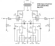
You are right. What I intent to mean is that to avoid extra high voltage across the CCS, we are use a resistor network similar to a "fixed bias" setup to lower the voltage of the grid. I attach a schematics to illustrate. The KT90s are biased at 70mA with the grid voltage set by the resistors. I select 10V as target. This can reduce the voltage across the CCS.
Attachments
- Status
- This old topic is closed. If you want to reopen this topic, contact a moderator using the "Report Post" button.
- Home
- Amplifiers
- Tubes / Valves
- CCS power amp bias