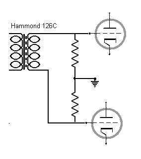
Well, he is talking about the IS-transformer (Hammond 126).
You cant use a 1:1 (single ended) bifilar wound interstage transformer as phase inverter due to high coupling capacitance (pry/sec).
Oh brother.
Thanks for clearing that up...
See what I think happened is he never bothered to read my post PRIOR to his first one, where I made clear how to
wire the IS:
Nazaroo said:"For the interstage, these resistors will provide ground reference,
and hence cathode bias, provided they follow recommendations for the RS242.
This is in case your interstage secondary doesn't have a c.t.

Since I had left the interstage more or less alone in my original,
but re-wired the OT, his comments sounded nuts.
Anyway, lots of good Push-Pull OTs also have bifilar windings,
such as the Macintosh designs, and almost all Plitron Toroids.
Of course if you only have ONE bifilar winding,
and no tapping or wiring options,
AND you want to use an IS tranny as an IS,
AND you don't want fixed bias,
then yeah.
You will have to ground your IS somehow,
but not necessarily at one side or the other,
as the above choice shows.
Jane said:You cant use a 1:1 (single ended) bifilar wound interstage transformer as phase inverter due to high coupling capacitance (pry/sec).
Now that its clear he was talking about the IS tranny,
things are at least starting to make sense.
In pro audio gear, I have used Jensens alot,
and even in some circuits I've bypassed tranny
using caps directly wired from primary to secondary on both sides!
That has to be a lot more capacitance than many are used to.
All that is required is balanced ins and outs.
Your point about going single-ended to balanced is well taken though.
I hadn't looked at his I.S. tranny closely,
and assumed he hadn't even bothered to note a center-tap.
This I.S. tranny is probably the wrong tool on a few levels.
A step-up tranny might be far more useful here,
if keeping the number of stages down is a design-goal.
Just one quick question:
Why can't his cathode-follower drive a capacitive load?
Or better, shouldn't he be using a 6SL7 here in the cathode-follower ?
Last edited:
Think a bit... What purpose that caps and resistors serve?
Sure:

hmm...
the 100k serves to self-bias the top tube.
Not sure I see the problem yet...
the .1 uF feeds the grid with the output of the bottom tube,
stiffening the supply B+ by increasing the effective value of the 750 R load to the bottom tube...
Nope, I'm missing it.
Although I didn't calculate these values,
I just threw them in.
The 100k was chosen to stabilize the 5998
as a grid leak resistor, perhaps its a bit low...
The .1 uF could probably be increased to .22 or .3
with good effect.
...nope not seeing it yet,
but tell me if I've still got something wired wrong.
Its been a long night.
...perhaps you missed my previous correction to the diagram? (post #26?)
Last edited:
Hello all.
Thought I would bump the thread by giving an update on this amplifier.Enclosed are my latest,semi final,schematics of both power supply and amplifier.I have upgraded a few things such as the bootstrapping that Wavebourn suggested,which works very well and gives a nice gain increase,and negates the need for a cathode bypass cap.Also,I have upgraded the OPT to an Electra print instead of the universal Hammond.The amp is being built as monoblocks and is sounding great to my ears,and is very quiet with almost undetectable hum on my 96db speakers.
As usual,Comments and suggestions are welcome,as this is all a learning experience for me,and thanks for all the help so far
Paul
Attachments
- Status
- This old topic is closed. If you want to reopen this topic, contact a moderator using the "Report Post" button.