6550 PUSH-PULL WITH CURRENT FEEDBACK
http://www.esafono.it/DOCMONO.pdf
is mine Yaqin MC-100B modified
that it's ideal for two monoblocks
the secondary 4 ohm and 8 ohm are in parallel
to increase current😱
http://www.esafono.it/DOCMONO.pdf
is mine Yaqin MC-100B modified
that it's ideal for two monoblocks
the secondary 4 ohm and 8 ohm are in parallel
to increase current😱
Hey Stee:
Dude you need to look for another supplier or stop going to pick and save for your drugs!
Art
Dude you need to look for another supplier or stop going to pick and save for your drugs!
Art
6550 PUSH-PULL WITH CURRENT FEEDBACK
http://www.esafono.it/DOCMONO.pdf
is mine Yaqin MC-100B modified
that it's ideal for two monoblocks
the secondary 4 ohm and 8 ohm are in parallel
to increase current😱
Paralleling up the 4R and 8R outputs will not increase current, the primary will see shorted turns so you'll end up with rather less current.
Stee,
Could you explain how the current feedback works, and why is it better than the conventional voltage feedback? I suppose the source impedance of the preamplifier should be low.
Could you explain how the current feedback works, and why is it better than the conventional voltage feedback? I suppose the source impedance of the preamplifier should be low.
I can't see any current feedback, just a resistor added in series with the output. I can see shunt feedback, which will give you an unusually low input impedance - almost certainly unhelpful and it may raise distortion in the source. You could try doing shunt feedback properly, with higher resistance values. There is a small advantage to shunt feedback: it removes common-mode distortion from the input stage, but this is usually so small that it can be ignored.
Paralleling 4 and 8 ohms secondaries is daft - you just use up power heating your copper windings.
Paralleling 4 and 8 ohms secondaries is daft - you just use up power heating your copper windings.
Almost 8K8 input impedance ! too low , you will need a preamp with very low output impedance to drive it .
thanks for your contributions
Meanwhile precise that it is not of a proposed
is a change that is playing very well
the feedback current functions as a real-time equalizer
(shunt power resistor 50W)
corrects the defect of natural bass tones
However, the input impedance becomes 2K2
the pilot with a V-DAC
the parallel between the secondaries is effective for the current delivered
really have to reconnect 8 windings (16 wires)
I highly recommend it
Meanwhile precise that it is not of a proposed
is a change that is playing very well
the feedback current functions as a real-time equalizer
(shunt power resistor 50W)
corrects the defect of natural bass tones
However, the input impedance becomes 2K2
the pilot with a V-DAC
the parallel between the secondaries is effective for the current delivered
really have to reconnect 8 windings
(16 wires)I highly recommend it
Attachments


Sorry, I don't understand. You mention a shunt power resistor but your circuit shows a series resistor. This has nothing to do with shunt feedback.
If your OPT secondary wiring works then it is not as you have described. Paralleling 4 and 8 ohm outputs will fail. However, some OPT (e.g. Sowter) have four identical secondaries which can be wired in different ways to get 1, 4, 9 or 16 ohms.
If your OPT secondary wiring works then it is not as you have described. Paralleling 4 and 8 ohm outputs will fail. However, some OPT (e.g. Sowter) have four identical secondaries which can be wired in different ways to get 1, 4, 9 or 16 ohms.
Taking the feedback from a current-sampling resistor will cause a boost in the voltage response at the bass resonant frequency of most speakers. Since that would be more agreeable with some speakers than others, it might be worth having a pot to vary between current mode and the usual voltage mode (variable damping).
I'd move the coupling caps and bias adjust components to the driver follower grids, then direct drive the output grid stoppers from the follower cathodes which would have the cathode resistors returning to the negative supply. Supporting grid current, that variation would increase the available output power without adding any parts or giving up performance at lower power. A switch on the screens to allow pentode mode would be handy if one ever had the need for the full 75 Watts or so output (100 if plate supply is bumped up to 600V).
I like the performance of inverting mode. Then the feedback takes care of hum and noise in the input stage and there are no common-mode issues. I would scale the input/FB values up a bit even though my current gear can drive 2.2K. (the grid is a virtual ground)
easy to try
Like all tube amp owners complain
pressure is always low enough
with this arrangement equalizes the system directly on the load current
compensating for the response of the whole amp / speaker in real time
must give up some power, however,
This is why I turned to minimum bias
22mA is a class AB
However DF96, some OPT (e.g.this Yaqin) have four identical secondaries in each output 4, 8 ohms which can be wired in parallel🙂
I repeat also
that the lifting-up of the cathode as internal feedback
(with positive signal)
should never be used
because it introduces emphasis
Last edited:
OK, so your OPT secondary wiring may be correct - just different from what you originally described.
OK, I can now see the current feedback. Sorry for my confusion. This will raise output impedance and cause 'one-note' bass with most loudspeakers, unless they have been designed with adequate mechanical damping - in which case they would be overdamped with a conventional amplifier.
OK, I can now see the current feedback. Sorry for my confusion. This will raise output impedance and cause 'one-note' bass with most loudspeakers, unless they have been designed with adequate mechanical damping - in which case they would be overdamped with a conventional amplifier.


Hello Stee, just practical point: ECC802 at frontend (if is the case) could be out of parameters concerning insulation voltage applied between heater and each cathode (if both cathodes uses the same heating circuit grounnded or close to zero) - may be ECC82 would be better here. I guess the B+ is about 450V and B3 about >350V (??) and upper cathode is then at >150V
Last edited:
srpp
at the moment I have installed two 6H30Pi
just change the heater wiring
of course the middle point of SRPP (out) is in any case half voltage
at the moment I have installed two 6H30Pi
just change the heater wiring
of course the middle point of SRPP (out) is in any case half voltage
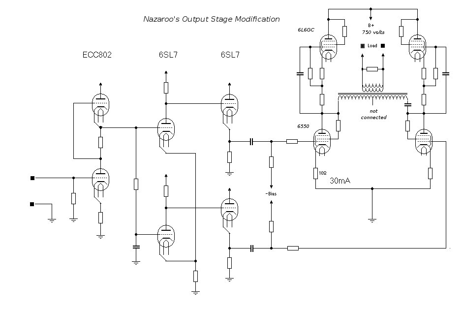
Hey Stee:
Feedback loops over 4 stages + transformer are just crap.
Try this instead. You will get far far lower distortion, for just two more tubes and couple of caps.
Click on pic to enlarge:
Feedback loops over 4 stages + transformer are just crap.
Try this instead. You will get far far lower distortion, for just two more tubes and couple of caps.
Click on pic to enlarge:
Attachments

Last edited:
A bit off-topic, Nazaroo, but what are you using to draw schematics?
I just used his posted schematic.
And GIMP (Linux)
Ahh - missed that. Thanks. I thought there might have been some clever program at work. No. Just a skilled user.
Ahh - missed that. Thanks. I thought there might have been some clever program at work. No. Just a skilled user.
I could write the clever program,
but I'd make both of us obselete.
- Status
- Not open for further replies.
- Home
- Amplifiers
- Tubes / Valves
- 6550 PUSH-PULL