Hi
I am going through KT88 Push Pull design , I have chosen my operating point as Ua=475 , Ia=70mA , Zaa=9k7. It should give me operation mainly in class A.
Please have a look at my loadline:
View attachment 282158
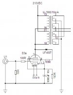
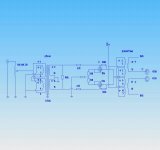
As a driver I am going to use triode strapped D3a in SE grounded cathode circuit plus LL1660 interstage transformer .Another option is LL1660 interstage transformer preceded by pair of D3a in LTP circuit , phase split by input LL1544A transformer .
Let's cut to the chase , to drive pair of KT88 with no grid current I need 2*53V=106V peak-peak (~34.5 VRMS) , lets assume that my interstage tranny has step down ratio 1:1.125 .According to that I need 38.8 VRMS from SE triode strappeed D3a. As D3a has gain of ~77 , it means that 500mVRMS from source drive my amplifier to full power.
Assuming that standard CD puts 2VRMS output , what will happen when I go above 500mV?
Regards
Hi
Let's cut to the chase , to drive pair of KT88 with no grid current I need 2*53V=106V peak-peak (~34.5 VRMS) , lets assume that my interstage tranny has step down ratio 1:1.125 .According to that I need 38.8 VRMS from SE triode strappeed D3a. As D3a has gain of ~77 , it means that 500mVRMS from source drive my amplifier to full power.
Are you planning on using any feedback? That will reduce overall gain and input sensitivity. I'm not at all familiar with interstage transformers, but if you still need a LTP phase splitter for driving PP, then the gain will be less than 1/2 the tube mu. You'll also need enough current to drive the Miller Capacitance of the KT88's.
Hi
From what I have read, negative feedback is not an option when it comes to transformer interstage coupling.But I might be wrong , I know very little about IT coupling - trying to learn .
There are 2 circuit options:

no need for ltp in this case , transformer does phase splitting.
and 2nd option:

in this case splitting is done on the input ,second transformer does interstage coupling.As you can see it uses ltp (I am planning to use ccs in the tail ), and here is my question, if grids are fed with already split signal , what would be gain of this stage?
Coming back to my loadline , any suggestions?
I use quite high tr impedance , instead of recommended 4k5-6k6 , I wonder why is not commonly used ( it gives so much of class A , power is low if compared to power dissipated in anodes ) , am I overlooking something?
I wonder if my operating point is right ,my voltage is quite high and going on characteristic to the right I am not sure whats happening there , as I have no curves below -60V.This makes me think if I have symmetrical swing on the negative part of signal .
From what I have read, negative feedback is not an option when it comes to transformer interstage coupling.But I might be wrong , I know very little about IT coupling - trying to learn .
There are 2 circuit options:

no need for ltp in this case , transformer does phase splitting.
and 2nd option:

in this case splitting is done on the input ,second transformer does interstage coupling.As you can see it uses ltp (I am planning to use ccs in the tail ), and here is my question, if grids are fed with already split signal , what would be gain of this stage?
Coming back to my loadline , any suggestions?
I use quite high tr impedance , instead of recommended 4k5-6k6 , I wonder why is not commonly used ( it gives so much of class A , power is low if compared to power dissipated in anodes ) , am I overlooking something?
I wonder if my operating point is right ,my voltage is quite high and going on characteristic to the right I am not sure whats happening there , as I have no curves below -60V.This makes me think if I have symmetrical swing on the negative part of signal .
Last edited:
Coming back to my loadline , any suggestions?
I use quite high tr impedance , instead of recommended 4k5-6k6 , I wonder why is not commonly used ( it gives so much of class A , power is low if compared to power dissipated in anodes ) , am I overlooking something?
I plugged a few values into Broskie's PP calculator, which calculates output power (as well as lots of other things like dissipation & distortion)..........
At 475 B+ and 70ma Iq,
OT 9700 gives about 26W total, although it gives 34W class A, but I think you'll only get 26W.
OT 8000 gives around 28W total, all class A
OT 7000 gives around 30W total, with about 24W class A.
and so on.........this trend continues with lower impedance output transformers
It does confirm my assumption , higher load seen by tubes it goes deeper into classA.
Your results for 475V are interesting , my interpretation is that there is still more of classA available if grid goes more negative but grid input signal is restricted by Vg=0V.
Question is how does it look like in tetrode classAB operation ?
Your results for 475V are interesting , my interpretation is that there is still more of classA available if grid goes more negative but grid input signal is restricted by Vg=0V.
Question is how does it look like in tetrode classAB operation ?
- Status
- This old topic is closed. If you want to reopen this topic, contact a moderator using the "Report Post" button.
- Home
- Amplifiers
- Tubes / Valves
- KT88/PP driver confusion