Should not be too much of a problem.
When secondary DCR is about 1.5 higher than primary DCR the same wire gauge has been used; when secondary DCR is much higher than 1.5 x prim, take care because secondary wire will be thinner and have less current capability.
These specs are normally within not too tight margins when you have a quality unit as far as core saturation is concerned; I'd say give it a try.
Last edited:
OK, you didn't say which ratio. A turns ratio of 1:1.5 would mean current is limited to 10mA or 20mA.
Could you tell me how did you come up with these current figures ?
I wouldn't think the current capability correlates with turn ratio.
Last edited:
If the transformer is a step up of 1.5 in impedance then this means that turns ratio is sqrt(1.5) - about 1.225. Assuming the current limit is caused by core saturation rather than copper heating, you can put 12.25mA or 24.5mA in reverse mode.
Are you sure this makes sense?
The current through the windings is not the same thing as the magnetising current. For any given frequency and voltage, the higher the current due to the load, the less likely the transformer is to saturate.
The magnetising current depends on the frequency, the voltage, and the primary inductance.
Your calculations seem OK. Basically, the power handling will be the same, and you are changing the reference from one winding to the other.
The more crucial question here is, will it have the same bandwidth? This is where that initial confusion between winding ratio and impedance ratio makes me wonder.
Essentially, the bandwidth will shift if the impedance seen by the windings is changed. Consequently, reversing the transformer and keeping everything else the same will change the frequency response.
But, when I woke up next day, I thought interstage, valve, DC current.
That's another thing that might have been more clear. The current limit is for DC bias current. To assume this relates to core saturation rather than power dissipation is unnecessary: it's a certainty. No secondary current arises from DC primary current, and so it is all magnetising. Flux density is proportional to turns*current, so the DC limit for the reversed transformer will be 1/1.5 times what it was.
Points made about bandwidth remain.
But, when I woke up next day, I thought interstage, valve, DC current.
That's another thing that might have been more clear. The current limit is for DC bias current. To assume this relates to core saturation rather than power dissipation is unnecessary: it's a certainty. No secondary current arises from DC primary current, and so it is all magnetising. Flux density is proportional to turns*current, so the DC limit for the reversed transformer will be 1/1.5 times what it was.
Points made about bandwidth remain.
I'm still having trouble with this:
Wire is rated strictly on current carrying capacity.
If only the primary is meant to carry the extra DC current (on top of the AC),
then one of the transformer maker's concerns will be current carrying capacity of the wire,
and he will use heavier wire in the primary, possibly even if the ratio were 1:1.
When you reverse an interstage xformer,
you are transferring the DC standing current to the other winding,
the one which could easily have smaller wire, especially if its a step-up.
Although the transformer doesn't care which side is given the source
of the AC signal, and which side passes it on, (reverse the general signal flow
and core saturation stays the same: think time reversal).
The transformer wire may care which side is carrying
the additional D.C. current, which is the whole reason
the transformer is needed (isolation).
It seems to me this must be checked on a transformer by transformer basis.
Indeed - by measuring the the wire resistance of the primary against the secondary - whilst cold - and accounting for the step up ratio which should be matched by the resistance ratio - you should have a fairly good idea of whether the reverse connection will work without passing any signal through the transformer.
My gut feeling would be that they will probably use exactly the same wire - to make their product as flexible as possible.
Shoog
My gut feeling would be that they will probably use exactly the same wire - to make their product as flexible as possible.
Shoog
They should be very nearly the same - so it seems it might not be such a good idea to reverse them.
Shoog
Difficult to say.
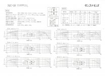
Primary DCR of 600 ohms is a good specification when tubes with Rp's in the 7k range (6SN7) can be used; it is very well possible that the choice of wire gauge was to get this DCR to keep copper losses small, and that actually the current rating has more to do with core saturation than wire gauge.
One experiment that can be done is to measure secondary DCR cold and after let's say 20 mA of DC current; when "hot" DCR is not much higher than cold DCR I don't expect problems by reversing primary and secondary.
I'm still having trouble with this:
Wire is rated strictly on current carrying capacity.
If only the primary is meant to carry the extra DC current (on top of the AC),
then one of the transformer maker's concerns will be current carrying capacity of the wire,
and he will use heavier wire in the primary, possibly even if the ratio were 1:1.
When you reverse an interstage xformer,
you are transferring the DC standing current to the other winding,
the one which could easily have smaller wire, especially if its a step-up.
Although the transformer doesn't care which side is given the source
of the AC signal, and which side passes it on, (reverse the general signal flow
and core saturation stays the same: think time reversal).
The transformer wire may care which side is carrying
the additional D.C. current, which is the whole reason
the transformer is needed (isolation).
It seems to me this must be checked on a transformer by transformer basis.
Yes, you're right. I hadn't thought about the power dissipation aspect of the DC.
I absolutely agree that transformers must be considered case by case. Too many parameters, and not enough common understanding for most people to make sensible predictions. OTOH, building valve amps seems to be about having fun these days, and the wrong transformer is more fun than the maths.
The original question is unanswerable without a lot more information. Had the information been available, the question wouldn't have needed asking.
- Status
- This old topic is closed. If you want to reopen this topic, contact a moderator using the "Report Post" button.
- Home
- Amplifiers
- Tubes / Valves
- Reversing Interstage Transformer