I think the OP realises that vibrator power supplies may bring problems, but don't swamp him with objections. He knows the sound could get a bit muddy, but he needs to do the best he can with his particular requirement for portability. When immersed in the music he still wants to hear air around the individual instruments.
..the OP schematic is a 4/8 Ohm loudspeaker amp with a R divider on the output for a headphone - lots going to waste there - especially for a battery powered project...
Yes, that is wasteful, I'd presumed the resistor divider shown on the original schematic was just for those wanting dual-use phones and speakers. I did intend to use an appropriate OPT and will probably wind my own, as tar-potting doesn't seem to be available as an option now.
...mechanical vibrator supplies are considered antiquated for good reasons - today the EMI from the mechanical contact opening is unacceptable; size, noise and efficiency can all be improved hugely with modern DC-DC SS designs with integrated chip controllers
I think a good many things that we still enjoy using are considered antiquated by some - including valves in audio equipment. I was told so in no uncertain terms by a university professor - though I don't share his point of view.
I hope to be able to deal with EMI issues to my own satisfaction. Contact breakers were used for many decades in car ignition and suppression was usually quite adequate, with the exception of boy-racers with copper leads and no resistor plug caps.
I'm still keen to hear from members regarding any practical advice they might have on construction issues relating to this particular circuit.
Last edited:
if you're winding your own ouput xmfr then I assume impedance scaling is in order
which then opens up tube choice - small signal tubes save doubly by using less heater power which quickly becomes a limitation with only ~ 1/2 Wrms audio power output requirement
car radio noise floor requirements are abysmal, "audiophile" headphone listening would require < ~ 20 dB SPL out of the headphone
vibrator supply operating frequency in the audible range makes the passive filtering requirement costly
Last edited:
Just so we get the correct idea..
Is this circuit submersible or amphibious?
Regards
M. Gregg
Well the title says "amphibious", so I was going with that...
Well the title says "amphibious", so I was going with that...
Is the battery carried back pack or in a vehicle?
Regards
M. Gregg
Is the battery carried back pack or in a vehicle?
Regards
M. Gregg
Something like this was what I had in mind:
Vehicle
Though I have to say that in the light of the comments I've received on here - thank you all by the way - I'm beginning to think that the design of this circuit is quite devoid of any consideration of the basic requirements of its stated purpose.
On a positive note, I understand that such vehicles are usually equipped with alternators, which might be helpful wrt the power supply requirements.
I think its important to understand that if you are looking at creating something to get you the old WW2 feel..the weight was incredible..and that was just the set not battery as well...I have tried one for fun..
If you are thinking New ways to do it thats a different thing..
The circuit as it stands in the 1st post just seems to me like a normal tube amp..car radios had different tubes and were not the normal standard 9 pin we all know..
Some old equipment was very intricate..and very complex..
So I think it depends what you are doing.
Regards
M. Gregg
....The circuit as it stands in the 1st post just seems to me like a normal tube amp..car radios had different tubes and were not the normal standard 9 pin we all know....So I think it depends what you are doing...
Well I thought that a "vacuum tube one-port class A amplifier - headphone amplifier amphibious circuit", as per the schematic page's title sounded as like something unusual, and possibly fun, one way or another....
It certainly does seem that it might not be the best circuit for the job, in the many ways mentioned so far on this thread, and also that the voltages involved are positively dangerous (the design indicates the negative rail to be grounded). But I believe it to be possible to catch fish en masse by passing electrical current through water, so perhaps the design might be of use to audiophile fishermen wanting bigger catches?
I suspect you need a decent Chinglish translator to discover what the person who uploaded that circuit thought he was saying.
Possibly seekic.com have a supplier with a warehouse full of the valves specified? And it does have headphones on the diagram....though where the sales angle in the amphibious bit comes from I really don't know.
Somewhere I think around here very recently I saw a design including a rudimentary switched-mode power supply. Definitely worth looking because good practical designs for HV audio are not common. Running heaters in series might save some power, as might higher-voltage heaters, because less current means less loss in the supplies.
The old buzzing contact design would be perhaps best mimicked quite efficiently by a free-running flyback converter, the one that regulates itself via its frequency. Not usually favoured for audio though because it's more convenient to use a fixed frequency that you can filter out more easily. Has anyone done a simple HV forward converter I wonder?
Other than the power supply, the other odd thing about the design is that it's a speaker amp, adaptable to headphones by the use of resistor dividers. I believe it is this practice, pretty much ubiquitous and almost mandatory in Europe, that makes so many head amps sound like afterthoughts.
A good valve amp is built round its output transformers, and these should be your main concern, especially if you want proper bass from a simple SET (or is it SEUL...it doesn't say what the screen ratio is AFAICS).
I'm doing pretty much the same thing, but without the battery-powered complication, and I don't need to worry about heater current. For my 62 ohm AKGs I have decided on a 5k:64 transformer from Sowter in the UK, who are happy to adapt windings at no extra cost. I'll drive these with 6CH6 but the circuit will equally accept EL84, both of which coincidentally result in unity gain between grids and headphones. I wouldn't really need a voltage amp were it not for winding resistance.
I really want good bass, which is not the traditional forte of SETs. However, the better winding ratio due to relatively high headphone impedance means that a wider frequency range should be available, and I decided to concentrate this on the bottom end. For that, lots of primary inductance is required, which means heavy cores and lots of windings which in turn leads to high primary resistance which messes up my target of 10:1 impedance ratio. As it happens this won't matter with AKG, but it will with some Sennheisers.
So I'll add a voltage amp stage and feedback to defeat the winding resistance and should end up with excellent bass, and possibly a slightly falling top end which will be good I think.
The OPT secondary will be in 4 equal sections of 4 ohms, giving efficient options of 4, 16, and 64 ohms, and a slightly uncomfortable 34-ish. So I could drive small efficient speakers too, although I think the top end might suffer.
So, concentrate on the power supply first, then the output transformers. Use common audio valves in the simplest way, as in your design but possibly without the UL connection...you have the perfect opportunity for the authentic SET sound so why complicate it.
Building will be mostly be a doddle. If you breadboard the amp, a final layout will come to you so forget about it for now.
A switching power supply will likely not be a doddle. I get scared experimenting with them. They seem to blow up easily, and so quick and disasterously that not much evidence remains of what went wrong.
Be prepared to spend money on the output transformers. You can experiment with toroidal power transformers backwards but they won't be ideal.
Don't electrocute yourself.
A bit more sensibly.....
Not electrocuting myself is something I always strive for. In fact, whilst it's probably heresy to say so in the Tubes/Valves section, mostly, I'd go for semiconductors for a headphone amp, with mains supply running through a frequently tested rcd. I'm quite aware that many folk love valve headphone amps, that's fine, good luck to you.
I should also make it clear, for those who might not yet have twigged, that it was the combination of high supply voltages, headphone amp, and "amphibious" that drew my attention to the circuit I linked to, I hope no Darwin awards result from it, but you never know.
Incidentally, the seekic.com site has hundreds of schematics, including many of historical interest, but I wouldn't buy components from them.
For those wanting a valve headphone amp whilst sharing my cautious attitude towards high voltage equipment and my head, and also by way of a little penance for mischievousness, might I suggest the following:
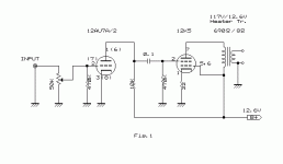
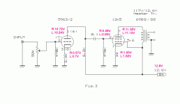
12K5 SE Low voltage stereo amplifier page 1
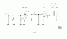
12K5 SE Low voltage stereo amplifier page 2
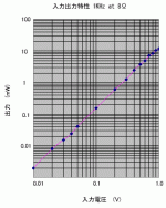
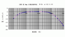
Though the text is in japanese, the schematics are clearly drawn and depict very simple, low power low voltage valve amplifiers. I've attached the images as eye-candy, and for non-japanese speakers, they're what you've got to go on. If the grid connections of the 12K5 look all wrong, look up "space charge".
For headphone use, the very convenient 117v mains-transformers-as-output-transformers would need to be changed, but being single ended amps, a gap-core opt might be better anyway.
Attachments
Not really. Just off-topic.Not electrocuting myself is something I always strive for. In fact, whilst it's probably heresy to say ...
No matter how silly the question, the answer is the same. Headphones are the only remaining legitimate modern application of the SET.
That is not to say there are not better ways of driving headphones.
There is no significant risk that you can demonstrate from using valves in properly-designed headphone amps, compared to any other valve amp.
To say that there is, is simply wrong and misleading. That's where the silliness is.
.....That's where the silliness is.
Oh Dear. Actually I didn't say that I could "demonstrate a significant risk from using valves in properly designed headphone amps."
mostly, I'd go for semiconductors for a headphone amp, with mains supply running through a frequently tested rcd.
I don't think I'm under any obligation to substantiate a claim I have not made, though I'm sure you'll correct me if I'm wrong. I wasn't trying to be inflammatory, merely stating my own personal preference, though it seems to have irritated you. I did state immediately afterwards:
I'm quite aware that many folk love valve headphone amps, that's fine, good luck to you.
I do hope I've
Fixed That For You
Not really. Just off-topic.
No matter how silly the question, the answer is the same. Headphones are the only remaining legitimate modern application of the SET.
Of the OTL I understand. Of the SET I do not.
Be prepared to spend money on the output transformers.
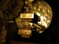
I'm a cheapskate, do you think these would be OK? After all for only 100mW I don't see the need for a big core.
Attachments
the wires are much clooser to you with headphones, I have yet to see a audio output xfmr claim "double insulated" construction
while as long as the headphone insulation/air space is fine you won't have problems - there is little question that the safety story is less compelling with heaphones powered from lethal supply V on your head vs the same powering speakers 10 ft away from your listening position
while as long as the headphone insulation/air space is fine you won't have problems - there is little question that the safety story is less compelling with heaphones powered from lethal supply V on your head vs the same powering speakers 10 ft away from your listening position
I'm a cheapskate, do you think these would be OK? After all for only 100mW I don't see the need for a big core.
Looks like a nice little pair. Where are they from, and have you taken any measurements?
Not tar-potted of course....
there is little question that the safety story is less compelling with heaphones powered from lethal supply V on your head vs the same powering speakers 10 ft away from your listening position
Electrocuted by your headphones - what a freak accident. I don't see it happening. And if it happens maybe you deserve to die (if you're that unlucky......a curse possibly).
Looks like a nice little pair. Where are they from, and have you taken any measurements?
Only measurements I did were with my metric tape. OT's were salvaged from a Telefunken radio.
- Status
- This old topic is closed. If you want to reopen this topic, contact a moderator using the "Report Post" button.
- Home
- Amplifiers
- Tubes / Valves
- Advice sought on thermionic headphone amp
