...at 25mA DC current.and measure the inductance with a good quality meter at 100 Hz, 1 kHz and 10 kHz.
...at 25mA DC current.
Yes, that would be best, but equipment measuring inductance with current flowing is not cheap

However "normal" measurements give a good indication, and when possible measure your choke to see if it has enough inductance (I think it is the limiting factor in your circuit).
However "normal" measurements give a good indication, and when possible measure your choke to see if it has enough inductance (I think it is the limiting factor in your circuit).
I agree with you. The choke's inductance is the only thing I see as the bass limiting factor. There might be a "hidden circuit" inside that affects the bass but I just don't see it.
It doesn't hurt to measure the choke first before gutting the circuit. Just my two pennies.
The choke cannot be the problem unless this particular 12B4 has unusually high anode impedance.
Do you see a more likely cause?
Even when the output capacitor is 0.33 instead of 3.3 uF, and the 33k input impedance of the Rotel amp is a 30k load together with the 470k load resistor, it is still a 16 Hz high pass which should not sound extremely bass shy.
There is not much in this circuit that can go wrong.
The change in load is so tiny compared to the 12B4 anode impedance that it can't possibly make any difference to the choke, assuming that the circuit is correct. Even an open circuit cathode decoupler would not raise the anode impedance by very much, as the 12B4 mu is so low. Assume a bad choke and a bad cathode decoupler: you still only get maybe 10% shift in LF cutoff when you change loads (10% is rough estimate - should be OK to within a factor of 2). Either the output cap is wrong, or the OP is not doing what he thinks he is doing or not hearing what he thinks he is hearing.
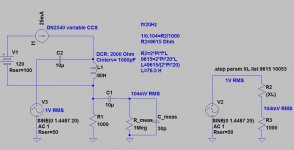
My measuring set:equipment measuring inductance with current flowing is not cheap
-simple power supply: 90VAC, diode, 220uF-100R-220uF
-simple CCS: DN2540 (heat sink), trimmer pot
-signal generator (1V, 10Hz-100kHz)
-RMS voltmeter
Attachments
Replace the choke with a good CCS. Then, even the nasty IHF 10 KOhm "standard" I/P impedance will not be a problem.
I really want to try the 12B4.
Any information or schematic as to a suitable CCS? I'm in the dark here...
Also, what's the B+ in your schematic?
And are the values of chokes in the PSU critical? I have some that are in the ballpark, but not exact.
Here are couple of simple CCS circuits:
Using two FET or transistor CCS with 12B4 is waisting of resources.
An externally hosted image should be here but it was not working when we last tested it.
An externally hosted image should be here but it was not working when we last tested it.
Using two FET or transistor CCS with 12B4 is waisting of resources.
Thank you for the schematics!
Do you mean that a 2-fet is more complexity than the 12B4 needs, and a simple CCS is sufficient?
Using two FET or transistor CCS with 12B4 is waisting of resources.
Do you mean that a 2-fet is more complexity than the 12B4 needs, and a simple CCS is sufficient?
Artosalo -
A few questions, in the CCS schematic that you show, does the potentiometer (variable resistor) need to handle any current? I.E., can it be a small trimmer pot?
And does this pot control the current, or is it a function of the pot in concert with the zener string?
Is there any reason why the zener can't be replaced with more LED's to make a 6.6v string?
Thank you,
Jim
The anode impedance of 12B4 is so low that the dynamic impedance of a simple one-fet CCS is more than sufficient. Typically 500k to 2Meg.
Depends. I thought the same thing until measurement confirmed improvement in both power supply ripple reduction, as well as IMD. Before and after attached; pictures of after condition in two images.
Attachments
The anode current of the tube passes thru the potentiometer, but since the voltage drop is only some three volts the power dissipation is small and the pot can be small too.
IRF9630 is a low cost enhancement type PFET and it has to be set to "open" stage with the "bias" voltage generated with the zener + diode string. The anode current of the tube forms a control voltage drop over the potentiometer which keeps the current constant. The diode in series (1N4148) with the zener is for temperature compensation.
I do not know how well the LED string can stabilize the voltage over wide temperature range, but this zener + diode works well.
Anyhow zeners need much higer current to operate.
Depends. I thought the same thing until measurement confirmed improvement in both power supply ripple reduction, as well as IMD. Before and after attached; pictures of after condition in two images.
I can not analyze your pictures. What is what ?
What are the circuits you compared ? And the results ?
In one of the plots the distortion component is some -110 dB below fundamental. What signal source you used ?
Last edited:
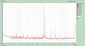
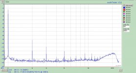
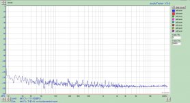
There is only one picture showing power supply ripple and IMD. That is the before. The other two are after the cascode was installed. You can see both THD as well as power supply ripple is changed when going from single FET to cascode. It does make a difference, even with a 12B4.
Source was just a transformer coupled DCX2496 with digital input, then feeding a P-P 12B4A preamp WOT.
Source was just a transformer coupled DCX2496 with digital input, then feeding a P-P 12B4A preamp WOT.
So you don't see the two 120Hz sidebands around the fundamental in this picture? Those are getting through the single FET CCS from the power supply. It is most simple to see they are gone in the other images, no heavy analysis required. No need to know every last detail about the circuit; one has a cascode, the other does not. Yes, these are way down near the noise floor of the soundcard, but they are real. I don't trust absolute distortion measurements down this low, so don't choke on the harmonics too much; that's not what is being compared.
Whether things are audible or not will be a neverending debate. It is one thing to claim audible differences that cannot be measured. These can be measured, and for that reason alone I strive to improve upon it. Never made claims about audibility; but I do make the claim there is measureable improvement with a cascode CCS.
Whether things are audible or not will be a neverending debate. It is one thing to claim audible differences that cannot be measured. These can be measured, and for that reason alone I strive to improve upon it. Never made claims about audibility; but I do make the claim there is measureable improvement with a cascode CCS.
Attachments

I do not know how well the LED string can stabilize the voltage over wide temperature range, but this zener + diode works well.
Anyhow zeners need much higer current to operate.
Thanks! I will try it as drawn first.
Zigzagflux -- Do you have a schematic of the CCS that you are showing these measurements? I would like to try that as well.
- Status
- This old topic is closed. If you want to reopen this topic, contact a moderator using the "Report Post" button.
- Home
- Amplifiers
- Tubes / Valves
- 12b4 bass rolloff problem