Hi,
I need some help with my mc10l no right ch sound.
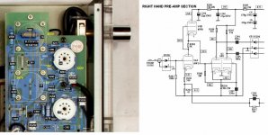
I have debugged and isolated down to the right ch preamp section by doing all the cable swap tests. Input selector and vol pot is also ok. Output transformer and the push pull stage is also ok.
On the look side, all the tubes looks normally lighted.
No wire wiskers of sorts on or below the pcb.
Any help will be greatly appreciated.
I need some help with my mc10l no right ch sound.
I have debugged and isolated down to the right ch preamp section by doing all the cable swap tests. Input selector and vol pot is also ok. Output transformer and the push pull stage is also ok.
On the look side, all the tubes looks normally lighted.
No wire wiskers of sorts on or below the pcb.
Any help will be greatly appreciated.
Thanks for the schematic with the reference voltage to look out for.
I've measured and found that R205 is in high impedance.
This 33K resistor does look very normal on my board thou, no burn marks whatsoever, Don't understand why it did fail.
My V4 tube was lighted thou.
1.8V wasn't present at R202 too.
R217 was measured to be 47ohms only. is the ESR of the cap in parallel playing an effect?
I shall be changing the R205 first.
Anything else should I look out for?
you re just measuring the 47R resistor that is in parallel with it (the cathode resistor). So it s normal.R217 was measured to be 47ohms only. is the ESR of the cap in parallel playing an effect?
Anything else should I look out for?
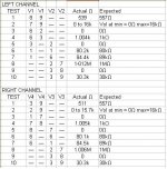
Don't forget that some easy checks can be made without removing any covers. With respect to the attached table, you can go round the input tube sockets with your multimeter - with the Amp switched OFF of course  AND allow plenty of time for any high voltages to discharge! Start by pulling V1 and V2 to check the Left Hand Channel, then V4 and V3 to check the right.
Remember that the tube socket numbering is now reversed as you are looking down onto the top, therefore the socket numbers go 1 to 9 counter-clockwise from the space. You may have to use some suitable single core wire to connect to the sockets if your multimeter probes are too thick.
Test 1 checks V1/V4 cathode circuit
Test 2 checks V1/V4 input circuit
Test 3 checks V1/V4 link
Test 4 checks V1/V4 1k Resistor
Test 5 checks V1-V2/V3-V4 link
Test 6 checks V1-V2/V3-V4 Anode Loads
Test 7 checks V1-V2/V3-V4 Anode Loads
Test 8 checks V2/V3 1M Ohm resistors
Test 9 checks V2/V3 link
Test 10 checks V2/V3 LTP Cathode Resistor
The readings taken as 'actual' were from a fully working amp.
Les
AND allow plenty of time for any high voltages to discharge! Start by pulling V1 and V2 to check the Left Hand Channel, then V4 and V3 to check the right.Remember that the tube socket numbering is now reversed as you are looking down onto the top, therefore the socket numbers go 1 to 9 counter-clockwise from the space. You may have to use some suitable single core wire to connect to the sockets if your multimeter probes are too thick.
Test 1 checks V1/V4 cathode circuit
Test 2 checks V1/V4 input circuit
Test 3 checks V1/V4 link
Test 4 checks V1/V4 1k Resistor
Test 5 checks V1-V2/V3-V4 link
Test 6 checks V1-V2/V3-V4 Anode Loads
Test 7 checks V1-V2/V3-V4 Anode Loads
Test 8 checks V2/V3 1M Ohm resistors
Test 9 checks V2/V3 link
Test 10 checks V2/V3 LTP Cathode Resistor
The readings taken as 'actual' were from a fully working amp.
Les
Attachments
- Status
- This old topic is closed. If you want to reopen this topic, contact a moderator using the "Report Post" button.
- Home
- Amplifiers
- Tubes / Valves
- No Right ch sound on yaqin mc10l