I have an EL84 amp that I'm not sure how to bias. I made a tester with a 1 ohm, 2 watt, 1% resistor in a plug saver tied between pin 3 and ground and when I first power it up it rises to about 18ma at the lowest adjustment on the bias pot and stays there for a few minutes but then starts to rise slowly when the tube starts to heat up and keeps climbing into dangerous territory. The voltage on pin 2 drops at the same time. When I remove the bias tool the voltage on pin 2 remains steady. It's a new amp so the caps all check out 100% on my esr meter. I don't remember my 6L6 amps ever doing this. Should I go with the cold bias setting before the tube heats up and starts rising and is there a reason why the 1 ohm resistor would cause this?
I previously posted a question about this amp in a different somewhat unrelated subject.
I previously posted a question about this amp in a different somewhat unrelated subject.
this is supposedly the same design, just an older version.Its difficult to answer,
Can you post or give a link to a schematic?
Sounds like your bias is way out...
Regards
M. Gregg
Attachments
Your connection through a plug saver won't work.
You didn't remove the direct cathode connection to ground in the amplifier.
You should install a resistor between pin 3 of each output tube and ground.
After the resistors are installed, you can measure the voltage drop across each cathode resistor and calculate the cathode currents.
a 10 ohm, .5 watt resistor on each cathode works well.
I cut pin 3 on the plug and soldered the resistor in between. All the other pins are direct.Your connection through a plug saver won't work.
You didn't remove the direct cathode connection to ground in the amplifier.
You should install a resistor between pin 3 of each output tube and ground.
After the resistors are installed, you can measure the voltage drop across each cathode resistor and calculate the cathode currents.
a 10 ohm, .5 watt resistor on each cathode works well.
So then you need to measure the voltage drop across that 10 ohm resistor installed in the socket saver, not between pin 3 and ground. Is that what you are doing?
I never used a 10 ohm, I used a 1 ohm when I made it and the meter is connected to either side of the resistor. My question is why is the current rising. It must be the bias tool like DF96 suggested.
what would be the best way to set the bias then if the tool doesn't work. someone suggested measuring across plug 1 and 17 and plug 2 and 17 on the schematic. To me that looks like it is across the B+. That doesn't make sense to me.EL84 a bit gassy, and the pin extender encouraging parasitic oscillation thus overheating?
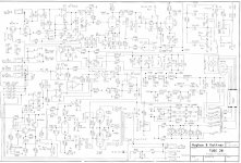
I think this is a better link to the schematic in a larger size.http://www.freeinfosociety.com/elect...ew.php?id=2288
Last edited:
here's a direct link to a larger size schematic. http://www.freeinfosociety.com/elect...ew.php?id=2288Its difficult to answer,
Can you post or give a link to a schematic?
Sounds like your bias is way out...
Regards
M. Gregg
Voltage on pin 2 (grid) dropping while anode current rises is a classic sign of oscillation. Grid stoppers may help. How does the designer say bias should be adjusted?
They don't. They suggest taking it to a service center. Would the initial steady point before rising be good enough? I also read to take the reading between plug 1&17 and 2&17. Does that make any sense?
Looks like the bias is set via R62/R63,
These are connected to a -DC supply trace it back passed C44..through R32...The value is fixed so it would seem there is no adjustment provided..It connects to 48V on the power Tx..
The only way to adjust would be to have two low value resistors in the cathodes (only so you can measure the volt drop and calc the current)and have a variable pot supplying the centre point of R62 /R63..
Standard DC fixed bias..")
Regards
M. Gregg
These are connected to a -DC supply trace it back passed C44..through R32...The value is fixed so it would seem there is no adjustment provided..It connects to 48V on the power Tx..
The only way to adjust would be to have two low value resistors in the cathodes (only so you can measure the volt drop and calc the current)and have a variable pot supplying the centre point of R62 /R63..
Standard DC fixed bias..
Regards
M. Gregg
Last edited:
R32, R69 and TR2 form a potential divider so bias is adjustable. Just unfortunate the designer did not seem to provide a way to measure the current.
Agreed didn't notice it..
Just had a quick look..Even if you use a removable resistor in the cathodes of the tubes as soon as you remove it the bias will be different.. I think if it was me I would put a low value power resistor in the Gnd connection between both Op tubes and measure it their Divide by 2 for the value..unless they have provided a removable link to be able to fit a temp resistor..?
Regards
M. Gregg
Last edited:
Voltage on pin 2 (grid) dropping while anode current rises is a classic sign of oscillation. Grid stoppers may help. How does the designer say bias should be adjusted?
I finally got a reply from H&K and they said ;
Ammeter must be set to 10A DC range
Connect Ammeter to plug 1 and plug 17 and after that to plug 2 and plug 17 on PCB
In both readings the rated values are 17ma - 20ma
Adjust bias with TR2
Do they mean to unplug the transformer from the board and connect the ammeter leads to the board or the transformer wires. I don't understand.
Are you sure that is the exact instructions?
Can you post the exact information they have given you?
Reason is if you set a meter to the 10A range it is realy a short between the probes just a low value shunt resistor in the meter..
So if you put your meter across the plug 1 & 17 you are going to short out the output Tx and burn out the OP tubes..same will happen on the 2 & 17 test..I could understand a voltage reading across the Tx and work out the current from the voltage reading..However you need to know the resistance value of the OP Tx or they need to tell you what voltage to set across the OP Tx..
If you remove the OP Tx and do the same test again you will stuff the OP tubes because there will be no load on the anode ie short circuit..
I think you need more information..The only way you can use the ameter is in series with the Op tx winding so the Tx resistance is still between the supply and the meter..Because plug 17 is the 400V B+ and the other two pins are the anode of the OP tubes..
From your link
http://www.freeinfosociety.com/electronics/schemview.php?id=2288
Ask the manufacturer if they can explain how this does not damage the OP tubes? Even if you can remove the Tx from the board and connect flying leads with the meter/ OP Tx in series, you still need the speaker load to prevent damage to the OP Tx.. (I bet they just measure the voltage (not current) across the Op Tx...)
Regards
M. Gregg
Last edited:
- Status
- This old topic is closed. If you want to reopen this topic, contact a moderator using the "Report Post" button.
- Home
- Amplifiers
- Tubes / Valves
- tester causing bias to rise?