Hello,
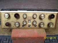
I came across an old Soundcraftsmen 5050 integrated tube amp that I want to rebuild. Problem being that I cannot find a schematic or for that matter hardly any reference to this piece online. If anyone has a lead on where I might find info on it that would be appreciated.
thanks, Mark
I came across an old Soundcraftsmen 5050 integrated tube amp that I want to rebuild. Problem being that I cannot find a schematic or for that matter hardly any reference to this piece online. If anyone has a lead on where I might find info on it that would be appreciated.
thanks, Mark
Hi Eli, thanks for responding. The tube compliment is as follows.
** 2 - NOS Mullard ECC83 Pre Amp
** 2 - NOS GE 7247 AF Amp Phase Inv.
** 4 - NOS Telefunken EL86 Power
** 1 - JJ GZ34S Rectifier
** 1 - NOS Telefunken EMM801 Indicator
I will provide photos when I can get my hands on a digi camera
thanks
** 2 - NOS Mullard ECC83 Pre Amp
** 2 - NOS GE 7247 AF Amp Phase Inv.
** 4 - NOS Telefunken EL86 Power
** 1 - JJ GZ34S Rectifier
** 1 - NOS Telefunken EMM801 Indicator
I will provide photos when I can get my hands on a digi camera
thanks
This is a super rare item, and fairly valuable - the best advice I can give you is to do as little as possible as necessary in order to get it up and running. (It should sound pretty good in proper working order.)
Usual candidates would include replacing electrolytics, and coupling caps if necessary.
Please post pictures.
Usual candidates would include replacing electrolytics, and coupling caps if necessary.
Please post pictures.
Get the JJ rectifier out of there, PRONTO! JJ has become notorious for quality control problems. The "zinger" making the rounds is Jamona Junk. Install a Sovtek 5AR4 and a pair of UF4007s to provide some PIV headroom.
I'm guessing the ECC83/12AX7s are in a phono section. The 7247/12DW7 is 1/2 a 'X7 and 1/2 a 'U7. A reasonable arrangement for that type is high μ section as a voltage amplifier and the low μ section as a "concertina" phase splitter that's DC coupled to the voltage amplifier. Look at the Dyna ST35.
I can't begin to guess why an indicator tube is part of an integrated amp.
Does the unit have tone controls?
@ Kevinkr, Would it's rarity explain the lack of info online? My goal is to get it back to it's original operating parameters. Unfortunately the filter caps have already been removed along with a couple other components which appear to be capacitors. So a schematic would be perfect, but I can't find one. I also got the matching Soundcraftsmen Simulcast 9520 MX reciever component. It's tube compliment is as follows.
** 1 - GE 6EB6
** 2 - " 6AU6
** 2 - " 6BZ6
** 1 - " 12AV7
** 1 - " Z2969
** 1 - Telefunken EAM-86
@Eli, The 12AX7s are for pre-amp cause it has an NPN transistor phono section.
The indicator tube is for the "Stere-auditor Output Balance Meters" on the face plate. It has tone controls, Right Bass and Treble and Left Bass and Treble along with a Presence Compensator control.
thanks
@Eli, I didn't know JJ has QC problem, I thought they were one of the better tube manufacturers out there. Is it all their tubes or just rectifiers? I have an old GE I'll use once the 5050 is up and running. Thanks for the heads up.
Jamona knows how to make good tubes. Heaven knows they did for quite some time. Sadly, the will to make a quality product has been missing of late, across all types. Until clear evidence of improved behavior is available, be extremely cautious about JJs product. Interestingly, JJ's 12DW7 was and may still be pretty good. Perhaps "salting away" a pair or 2 that are purchased from a RELIABLE seller is in order.
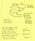
I've uploaded the series SS diode "trick". Follow the layout, but use UF4007s, not NASTY 1N4007s. The tweak may be critical with Sovtek 5AR4s and does not hurt, when an OS tube is used.
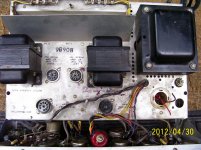
I suspect the missing filter cap. is 2 section, as I see 2 red wires. The 5AR4 data sheet tells us what the limiting values are. Jim McShane, a VERY reliable seller of tubes and parts, stocks a F&T brand 500 WVDC 50 μF./50 uF. part that rates to be suitable.
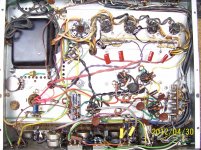
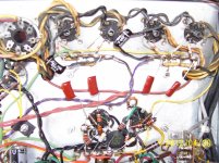
If a restoration that's close to OEM is to happen, hand tracing out the schematic may be necessary. OTOH, functionally refurbishing the unit to perform well is somewhat easier. The building blocks available are well understood and good sound can be anticipated.
The uploaded photos provide at least 1 clue. I see a "top hat" diode connected to a potentiometer. That suggests the O/P tubes use "fixed" bias and only a single adjustment is present. That imposes a requirement that all 4 "finals" be very closely matched in both gm and cathode current. Can you say increased costs?
From what I've been able to gather, the amp and tuner date from the end of the 1950s. The BJTs in the phono section may be germanium, not silicon. How many transistors are there in each channel? Sorry, the tuner is unimpressive. It predates FM MPX and has (IMO) an inadequate tube complement. The tuner's value may be exclusively historical.
Attachments
I have a single ended 6BQ5 Soundcraftsmen 2020 integrated amp. I ended up using the schematic of the Eric 3460P as they are the same thing. Maybe Eric made the amp for SC? Here's an Eric 3560T integrated amp with striking resemblance to your 5050. Perhaps you can purchase the schematic from the seller for servicing.

Follow the layout, but use UF4007s, not NASTY 1N4007s.
UF4007s may be the correct choice if starting from scratch, but I am using 1N4007s for the 5AR4 in my 6CA7 PP build and my THD is less than 0.055%, and hum at the speaker terminals is less than 1mV, inaudible.
UF4007s may be the correct choice if starting from scratch, but I am using 1N4007s for the 5AR4 in my 6CA7 PP build and my THD is less than 0.055%, and hum at the speaker terminals is less than 1mV, inaudible.
The UF **** diodes will reduce noise, they won't affect hum or THD. Your measurements are excellent, they just aren't the measurements that dictate why a better diode is a good choice. Do a search for "PN burst noise" or "diode noise", you'll turn up a lot of good info.
@Eli, I didn't know JJ has QC problem, I thought they were one of the better tube manufacturers out there. Is it all their tubes or just rectifiers? I have an old GE I'll use once the 5050 is up and running. Thanks for the heads up.
Let me second Eli - get the JJ 5AR4/GZ34 out of there.
This is a super rare item, and fairly valuable - the best advice I can give you is to do as little as possible as necessary in order to get it up and running. (It should sound pretty good in proper working order.)
Usual candidates would include replacing electrolytics, and coupling caps if necessary.
Please post pictures.
What Kevin said! Also, take good care of the EL86s, they aren't cheap and common like they once were.
I see the chassis has two empty holes - the small hole was for a large power resistor the was mounted to the chassis; the larger hole was for a multisection can cap. I see a grey Illinois cap under the chassis that isn't original and I also see a terminal strip under the larger hole to the left of the Illinois cap in the pic - it leads to the top hat diode and pot Eli mentioned. It's certain that is bias supply parts that have been relocated.
I think a proper new can and a better job of implementing the bias supply is in order. I can likely help if you don't have another source for the parts.
I think a proper new can and a better job of implementing the bias supply is in order. I can likely help if you don't have another source for the parts.
- Status
- This old topic is closed. If you want to reopen this topic, contact a moderator using the "Report Post" button.
- Home
- Amplifiers
- Tubes / Valves
- Soundcraftsmen 5050