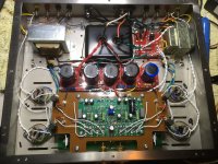
Fellows: I finally built the board I showed in post #38 and it works great. See the photos of my first trial build controlling a pair of 6BQ5s on a Hammond AO-43 organ donor amp. By "great" I mean that it keeps the bias balance and stability rock solid. What I don't know and can't really test is whether there are any sonic impacts.
Another odd thing is that on power up the current in the output tubes runs up briefly until the controller kicks in. I assume that's an artifact of the slow reaction to large swings needed to keep its effects sub-audible. It doesn't trouble me because it's transient and not too much over current.
NOTE: My layout in post #38 has a voltage quadrupler power supply since I had originally meant to run it off the 6.3 v filament transformer. However, you'll notice that on the quadrupler one leg of the 6.3 Vac input is grounded, which means it needs a dedicated power transformer (albeit tiny) or a spare winding on your power transformer. That is, unless you've got an odd amp with one leg of the filament winding grounded, or maybe a 12.6V filament winding with grounded center tap.
Attachments
A link to Robs page for the schematic which Warmsound says he used as a basis.
Motional feedback intro
I'm not sure the balance control would be required. If teh same demand is applied to both channels then they should balance, Rob was using a Plitron VDV2100 CFB/H torroidal output tranny so he was very concerned about balance to avoid saturating the tranny.
To prevent overshoot at switch on you need to delay application of the reference voltage for say 30 seconds.
Cheers,
Ian
Thanks Gingertube, I'd forgotten about Rob's description of the startup delay feature (even though I labelled it right there on my board layout.  ). I guess I'll have to implement that next.
You're correct, strictly speaking the balance pot isn't necessary, but is included to compensate for tolerances in components. Pots are cheap so I included it. Various LM324s I tried were quite different so it was worthwhile, not to mention all the peripheral resistors, diodes and caps.
). I guess I'll have to implement that next.You're correct, strictly speaking the balance pot isn't necessary, but is included to compensate for tolerances in components. Pots are cheap so I included it. Various LM324s I tried were quite different so it was worthwhile, not to mention all the peripheral resistors, diodes and caps.
Guido Tent's bias board has an input for the HV supply and the bias board only starts trying to set the bias about 45 seconds or so after the HV supply comes up. Until then, it sits at -85V. It moves at a rate of about 1 volt per second after that until it achieves the target bias current. A single pot sets the target current for four tubes.
For the board I made of the Broskie circuit, I had planned on having a microcontroller that would control some power sequencing on the amp. This would also hold the bias board at a fully negative voltage until the power tubes were warm enough to conduct, then I would let the circuit go to work.
For the board I made of the Broskie circuit, I had planned on having a microcontroller that would control some power sequencing on the amp. This would also hold the bias board at a fully negative voltage until the power tubes were warm enough to conduct, then I would let the circuit go to work.
I KNOW this is a very old thread with a last post of early 2015 and I apologise in advance for "Frankensteining" it. However, it is exactly what I am currently interested in and it seems pretty much unique on the internet. I am considering building in auto-bias to a Marshall guitar amp with a pair of EL34s currently running at 35mA fixed bias with a 1ohm sensing resistor permanently in the cathode for use while bias setting.
Some will no doubt ask "Why?" The answer is that it is a useful precursor to building in power scaling with a variable B++ on the output stages. Marshalls are loud! To keep their best tone they need to be driven. This means small pub/club gigs are difficult as you are constantly on the edge of sounding flat with the Master Volume down so low. I do use additional calculated load resistors to slug the output down but that again tends to lead to a slightly lifeless sound, and I promise you I am not an overly fussy self-confessed "tone freak", it just has to sound reasonable and feel lively under my fingers. When dropping the B++ voltage on the output to reduce output power and enable the output valves to saturate earlier, bias needs to be trimmed and auto-bias, as opposed to the usual second external pot, seems as good a way as any to lock the whole bias setup in place. It seems so much better to have a circuit which will reset itself to the dialled in bias current no matter what the HT voltage is set to.
I do have a full career in electronic design so I am pretty well aware of what is being said about all of the systems referred to. I have the RMS Acoustics links with the theoretical info on the historical systems, it was actually searching around them that led me to here. If the original posters of the last page or two of this thread are still walking the planet ( ) and are inclined to give a little more info I would be very grateful.
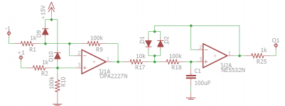
I am drawn to Gingertube's suggested circuit in post #32. It's neat, cheap and to the point and the principles are simple. I've simulated it in LTSpice with bog standard components, (TL072, 1N914, 2N5401, 2N5550), and played with it for a couple of days in LTSpice and it looks good. As I said, my cathode sensing resistor is 1ohm imposed by the existing amp design which I would rather not change. I tested increasing the gain of the first opamp stage to 1000x by dropping the two 22k resistors to 2k2 to keep the first stage working at 1V/mA. It definitely performs better that way than just leaving it at 100x with the original values while working with a 1/10 cathode sensing voltage. Symmetry at the various stages was not good that way so drift was considerably higher.
I have run up the simulation with a simple triangular tone burst signal to check drift after drive. (I find using a triangular signal where there is no obvious penalty shows up non-linearities to the eye much more easily. The various signals at stages of this circuit are very easy to understand for example.) After a 5sec burst of 30V on the EL34 grid showing peaks of 235mA the bias current of 35mA is consistently 0.175mA low and recovers in around 2.5s. For a prolonged 20s burst it drops by 0.443mA and recovers in pretty much the same time. That is pretty good in my experience, probably far better than the amp's original bias circuit and output valves would show, but I am interested in the reasons why it should drift in terms of this circuit.
One issue that I can actually see causing this is a definite slight asymmetry remaining in the clipped signal around the diode clamped integrator at the junction of the diodes and the two 470k resistors. It is slight but will lead to a definite gradual drift downwards from the set level. Has anyone actually used this circuit and found similar results in practice? Is there any reliable way of perhaps alleviating this slight asymmetry or improving performance? Better components such as the opamps are a possibility of course and I will go into that next.
Some will no doubt ask "Why?" The answer is that it is a useful precursor to building in power scaling with a variable B++ on the output stages. Marshalls are loud! To keep their best tone they need to be driven. This means small pub/club gigs are difficult as you are constantly on the edge of sounding flat with the Master Volume down so low. I do use additional calculated load resistors to slug the output down but that again tends to lead to a slightly lifeless sound, and I promise you I am not an overly fussy self-confessed "tone freak", it just has to sound reasonable and feel lively under my fingers. When dropping the B++ voltage on the output to reduce output power and enable the output valves to saturate earlier, bias needs to be trimmed and auto-bias, as opposed to the usual second external pot, seems as good a way as any to lock the whole bias setup in place. It seems so much better to have a circuit which will reset itself to the dialled in bias current no matter what the HT voltage is set to.
I do have a full career in electronic design so I am pretty well aware of what is being said about all of the systems referred to. I have the RMS Acoustics links with the theoretical info on the historical systems, it was actually searching around them that led me to here. If the original posters of the last page or two of this thread are still walking the planet (
) and are inclined to give a little more info I would be very grateful.I am drawn to Gingertube's suggested circuit in post #32. It's neat, cheap and to the point and the principles are simple. I've simulated it in LTSpice with bog standard components, (TL072, 1N914, 2N5401, 2N5550), and played with it for a couple of days in LTSpice and it looks good. As I said, my cathode sensing resistor is 1ohm imposed by the existing amp design which I would rather not change. I tested increasing the gain of the first opamp stage to 1000x by dropping the two 22k resistors to 2k2 to keep the first stage working at 1V/mA. It definitely performs better that way than just leaving it at 100x with the original values while working with a 1/10 cathode sensing voltage. Symmetry at the various stages was not good that way so drift was considerably higher.
I have run up the simulation with a simple triangular tone burst signal to check drift after drive. (I find using a triangular signal where there is no obvious penalty shows up non-linearities to the eye much more easily. The various signals at stages of this circuit are very easy to understand for example.) After a 5sec burst of 30V on the EL34 grid showing peaks of 235mA the bias current of 35mA is consistently 0.175mA low and recovers in around 2.5s. For a prolonged 20s burst it drops by 0.443mA and recovers in pretty much the same time. That is pretty good in my experience, probably far better than the amp's original bias circuit and output valves would show, but I am interested in the reasons why it should drift in terms of this circuit.
One issue that I can actually see causing this is a definite slight asymmetry remaining in the clipped signal around the diode clamped integrator at the junction of the diodes and the two 470k resistors. It is slight but will lead to a definite gradual drift downwards from the set level. Has anyone actually used this circuit and found similar results in practice? Is there any reliable way of perhaps alleviating this slight asymmetry or improving performance? Better components such as the opamps are a possibility of course and I will go into that next.
Just buy one of these from Pavel. Excellent board.
Automatic bias supply module for two push-pull (PP) tube AB-2. Dimensions 74x42 mm TES
Automatic bias supply module for two push-pull (PP) tube AB-2. Dimensions 74x42 mm TES
Just buy one of these from Pavel. Excellent board.
Automatic bias supply module for two push-pull (PP) tube AB-2. Dimensions 74x42 mm TES
Absolutely! I went to the trouble a few years ago looking at all the autobias schematics, LTspicing them, etc. Then, boom, the board above arrived on the scene. I have one and it is fabulous.
Thanks for the heads up on the Pavel unit. It looks fine but I really wanted to make my own as I can then tailor the PCB to piggyback the main PCB in my amp. Removing only a couple of main components from the existing bias circuit and fitting them onto the new PCB allows me to place pads so I can standoff my own board just above the original using short stiff copper wires from the vacated pads. It always makes for a neat and reliable setup rather than mounting a PCB somewhere convenient and running more wires around to tie things up.
That said, I am certainly interested in that Pavel AB-2 board. Do you know what the smd chip is that they use? They seem to be very careful to not post pics of it with that visible. If we knew that we might be able to hazard a guess as to how different it actually is.
That said, I am certainly interested in that Pavel AB-2 board. Do you know what the smd chip is that they use? They seem to be very careful to not post pics of it with that visible. If we knew that we might be able to hazard a guess as to how different it actually is.
Albertb,
I would be careful lowering B+ in an amp that the screen voltage also gets lowered. Especially in a guitar amp, I would think that you don't want your load line going below the knee of the curves where the screen current gets really high and damaging the screen grid from overheating if you overdrive the amp.
I made some boards very similar to the circuit in post #32 (after buying one of the TentLabs units which is in use in my main hifi amplifier). The circuit works great, I used it in an amp I made for my brother and various bench experiments. The clipper circuit makes the drift very slow and I have observed what I consider to be negligible variations in output even with ear-bleeding levels of sound coming from the amp. The variations were detectible, though. It does drift a little bit. The clipper circuit doesn't totally stop that from happening.
I selected different opamps for the version I made. I think there is room for a lot of improvement over what the circuit calls out, and what was in the TentLabs module. I'd be interested in what chips the other module uses as well. Maybe they found one with better cost/performance tradeoffs than I did. I think the one that I used cost seven bucks or something. I think I went for precision in the amp that does the voltage comparison (precision=$$) and low noise for the other stage.
That's really interesting to hear SpreadSpectrum, thanks for the info. I'm still at the simulation stage and I'm getting a feel for how each section affects factors in use.
As I said, I am sticking with a 1ohm sensing resistor in the cathode as per the original amp design so I've increase gain to 1000x with 1k/1Meg resistors around the first stage. It doesn't seem to have any bad effect. I've redesigned the output stage to take out the offset caused by the PNP transistor Vbe. I've also looked at improving symmetry within the two stages as I found this to be the main cause of drift during drive.
As you would expect the stability of the overall controlling voltage on the 47uF cap has a reliance on the symmetry of the diode clamped signal both in time terms which we want and in level which we don't. This in turn is helped by symmetry in the output of the first stage and there is the rub. As that stage basically clips within the opamp at the moment I found an improvement when I added a pair of back to back 9V1 zeners across the feedback to limit its output there and make it more symmetrical. This removes a reliance on rail to rail opamp symmetry which is never really great. The LM358s mentioned are very poor in that respect with big +ve and -ve differences quoted within their datasheet.
Lowering the two 470k resistors seems to help too. I currently have them set at 22k and 220k which seems to work well. Lowering the first resistor drives the two clamp diodes a little harder currentwise. This reduces their reaction to voltage level asymmetry in the signal from the first stage and tidies up the voltage they supply to control the DC level on the cap without stressing the first opamp at all. Lowering the second speeds up the response of the integrator a bit which helps with recovery after a prolonged burst of high power.
I am also playing with the output stage. I have currently swapped to a simple PNP long tailed pair with its tail set at +12V from the opamp supply. I can then make sure the integrator output can work around 0V and takes no real time to stabilise from an odd level at switch on. It can easily be trimmed for level via the other transistor base. This works really well with just a simple pair, (the -ve is from the existing Bias voltage setup so it can't be worse noisewise than the original circuit), but I'll improve this with a little more gain once I have time.
I know this is only the simulation stage but the whole thing seems to work very well. The bias level is stable at switch on without any oddities in the Vk/Ik value. I can't model warm up with the EL34 models I have but it sets immediately to the correct bias current meaning the warm up should remain largely a factor of the valve just as it is now. During prolonged drive there is a slight increase in Cap/Integrator voltage levelling off at +1.9mV over about 10s which leads to a drop in bias current. Bias current value is difficult to measure while it is actually being driven with a continuous signal but when the signal ends (at a clean 0V) the cathode current level exits down by 600uA. It recovers from that with a slight well damped droop and rise within 0.05s.
It's looking promising at this stage but there is a fair bit to go. I do take the point made by the other guys that there are commercial units on the market which do this job well but it's really an interesting and fun little project. And, of course, they can't be customised to fit into the amp I'm working with to the same extent.
Last edited:
Here is the version I built. This is one part of a board I made so that I could configure the servo for various purposes with jumper wires. I also wanted to be able to use it to bias voltage amplifier states using a sample of the plate voltage. Obviously, the voltage still needs to be amplified for a power tube. I used a simple pnp transistor amplifier like the circuit referred to earlier but I omitted the npn follower.
I think I used 2-5 Ohm current sensing resistors in the applications that I tested with this.
I'd be interested to see what you come up with in the end. I never simulated or played much with the design, just made some changes that I thought made sense.
I think I used 2-5 Ohm current sensing resistors in the applications that I tested with this.
I'd be interested to see what you come up with in the end. I never simulated or played much with the design, just made some changes that I thought made sense.
Attachments
Yeah, I just read it from Van der Veen's book and tweaked the circuit values to suit what I thought might work a little better. I thought the impedances were just a little high and some better opamps could be used.
Sounds like Albertb is giving it a thorough optimization treatment. I hope he shares his results when he is done.
Sounds like Albertb is giving it a thorough optimization treatment. I hope he shares his results when he is done.
I tried to improve auto-bias for convenience sake of a SE output stage, and found that it not worth it. When the output stage approaches clipping it's average current changes. Auto-bias trying to keep it stable causes audible dynamic distortions. The best bias for output stages from sound perspective is independent from current. Constant current bias is the worst scenario. Plain dumb shunted by cap resistor is kind of a compromise, but a part fixed-part cathode resistor bias is a good compromise.
However, if to implement a current sensor in pauses, and S/H when it plays the music, it may work well, even for class AB2 stages.
However, if to implement a current sensor in pauses, and S/H when it plays the music, it may work well, even for class AB2 stages.
Well, the amp I tested this on was a (Class AB) push-pull KT88 amp with direct-coupled plate-grid feedback on the output tubes. Bias voltage was to a mosfet buffer gate and was ~-137V when properly set.
With the circuit as I built it, I was getting ~100mV of bias voltage drift after ear-bleedingly loud music passages. Loud electronic music with long, sustained bass notes. This drift was obviously very low frequency and I don't see how it could be audible in any way given the small magnitude compared to the required bias voltage.
I really like having the peace of mind that my amp with the Plitron transformers is always in good balance to stay away from the degradation in performance that imbalance would cause.
But there is certainly an argument for simplicity. Unfortunately, building a simple, well known circuit doesn't challenge the mind.
- Status
- This old topic is closed. If you want to reopen this topic, contact a moderator using the "Report Post" button.
- Home
- Amplifiers
- Tubes / Valves
- Broskie auto bias