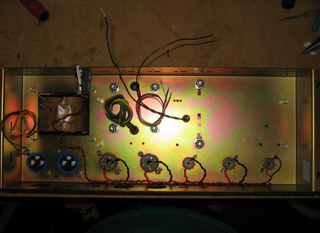
looking over photos of DIY projects on the net, and hearing the many stories about hum, makes me want to offer some observations that might help amateur builders.
Understanding the problem of tube heaters and hum is the first step toward ensuring your wiring job will be good enough to give happy results (no hum).
(1) The heater supply is usually A.C. (alternating current), a 50 or 60 cycle voltage taken from a winding off of the power-supply transformer. As such, it is usually more or less a sine-curve (but often with additional components, harmonics), but can actually appear as gross as a sawtooth depending upon the quality of your line voltage.
(2) For hi-fi and musical applications, the heater lines unfortunately provide a way in for noise from the mains (random hash, transients), and also radio frequency noise (RF), because the wires can also act as antennae, picking up noise from nearby motors and other equipment.
(3) So even if you don't convert your Alternating Current (A.C.) power to Direct Current (D.C.), you will still want to have some filtering and protection from line and radio noise.
(4) Also, if you don't convert to D.C., the 60 cycle A.C. hum will leak into other nearby circuits through the electromagnetic field coming off the heater wires, unless you take some precautions.
(5) As well, noise from other parts of the amp (the High Voltage HV supply, the screen supply and bias supplies) can also pick up and inject noise back into the heater lines.
(6) Many people don't bother to convert A.C. to D.C. for the heaters, and so other methods must be applied to minimize hum and noise. This is sometimes a cheaper solution.
In any case, hum and noise remains a problem with amplifier circuits, so basic strategies should be used.
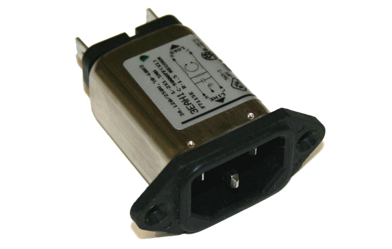
Regardless of whether or not you convert A.C. to D.C. (removing most of the hum), the Mains coming into the amp should be filtered and/or isolated from line noise. This can be done with a basic capacitor network on the lines.
It can be built into the line plug:
-----------------------------------------------------
Next, comes the layout of the heater wiring itself.
(1) The A.C. supply wires are twisted together, to collapse and minimize the field around each. At the same time as current flows in one direction on one line, it is returning in the opposite direction on the other line, and the two fields interact and cancel each other out.
(2) But there is ANOTHER reason why the wires are twisted together, which is often forgotten or neglected: It also stiffens the delivery system and minimizes movement of the wires. What movement? Any motion in a wire carrying current, or in a magnetic field generates a signal, or creates a coupling field. The motion can be very small, almost invisible, as in a guitar or violin string. It will still be very significant here.

The practice of twisting wires is also done to greatly stiffen them, minimizing motion and coupling fields.
(3) This is also the reason why SOLID wire (such as 18 to 14 gauge) should be used for heater leads. In fact, any and all electrical activity has an impact on all metal in the area, and in case you haven't guessed it, will also cause physical forces of motion on the wires. Here we DON'T want flexibility, but rather stiffness.
If you doubt this, or think it is insignificant,
try loosening the bracing bolts on your power transformer,
and listening to the horrible vibrating rattles as the E-I sections bounce around.
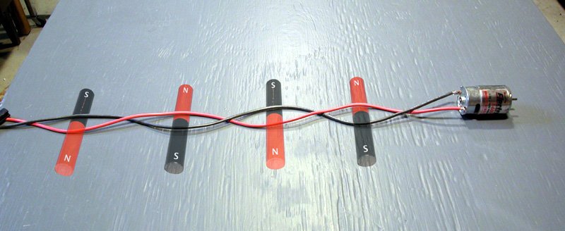
(4) Getting back to the theory behind twisting the wires, We want to recognise also that the number of twists is also strongly related to the DISTANCE to the next object that might pick up the signal, by the Inverse Square Law:
Quote:
"The circuit is essentially a coreless electromagnet with only a single turn of wire. By twisting the wires, we produce many small electromagnets, instead of one large one. Furthermore, these many small magnets are pointing in alternating directions. If we were very close to one of these magnets, we could still detect it, but once we are a small distance away, the adjacent opposing magnets will cancel it out (figure 3)."
Thus we want as many twists as possible (per inch), to minimize the proximity effect to other nearby objects.
On the other hand, if you twist the wires too tight, you can also short them or break them or weaken them to the point where they generate resistance and heat unevenly, so there is a limit to how much you can coil / twist the wires before you risk damaging them.
Now we are ready to understand why many seemingly good efforts at heater-wire dressing fail.
The hum is directly related to distance:
(1) The most sensitive components are the ones closest to the heater wire. That would be the area right around the socket! This is typically where the twisting-dressing technique is done the most poorly and sloppily!
(2) Wires at a right-angle to the heater-wire are the least sensitive to hum. Often wires and components are laid out badly in regard to this obvious issue: orientation.
(3) Other components may or may not be more or less sensitive to heater hum depending on orientation. THERE ARE NO general rules for this. For instance, its a bit tricky to orient a coil (or a cap!) for minimum hum, because it has a 3-dimensional field! Some components will be sensitive in ANY orientation, and must be shielded.
Understanding the problem of tube heaters and hum is the first step toward ensuring your wiring job will be good enough to give happy results (no hum).
(1) The heater supply is usually A.C. (alternating current), a 50 or 60 cycle voltage taken from a winding off of the power-supply transformer. As such, it is usually more or less a sine-curve (but often with additional components, harmonics), but can actually appear as gross as a sawtooth depending upon the quality of your line voltage.
(2) For hi-fi and musical applications, the heater lines unfortunately provide a way in for noise from the mains (random hash, transients), and also radio frequency noise (RF), because the wires can also act as antennae, picking up noise from nearby motors and other equipment.
(3) So even if you don't convert your Alternating Current (A.C.) power to Direct Current (D.C.), you will still want to have some filtering and protection from line and radio noise.
(4) Also, if you don't convert to D.C., the 60 cycle A.C. hum will leak into other nearby circuits through the electromagnetic field coming off the heater wires, unless you take some precautions.
(5) As well, noise from other parts of the amp (the High Voltage HV supply, the screen supply and bias supplies) can also pick up and inject noise back into the heater lines.
(6) Many people don't bother to convert A.C. to D.C. for the heaters, and so other methods must be applied to minimize hum and noise. This is sometimes a cheaper solution.
In any case, hum and noise remains a problem with amplifier circuits, so basic strategies should be used.
Regardless of whether or not you convert A.C. to D.C. (removing most of the hum), the Mains coming into the amp should be filtered and/or isolated from line noise. This can be done with a basic capacitor network on the lines.
It can be built into the line plug:

-----------------------------------------------------
Next, comes the layout of the heater wiring itself.
(1) The A.C. supply wires are twisted together, to collapse and minimize the field around each. At the same time as current flows in one direction on one line, it is returning in the opposite direction on the other line, and the two fields interact and cancel each other out.

(2) But there is ANOTHER reason why the wires are twisted together, which is often forgotten or neglected: It also stiffens the delivery system and minimizes movement of the wires. What movement? Any motion in a wire carrying current, or in a magnetic field generates a signal, or creates a coupling field. The motion can be very small, almost invisible, as in a guitar or violin string. It will still be very significant here.

The practice of twisting wires is also done to greatly stiffen them, minimizing motion and coupling fields.
(3) This is also the reason why SOLID wire (such as 18 to 14 gauge) should be used for heater leads. In fact, any and all electrical activity has an impact on all metal in the area, and in case you haven't guessed it, will also cause physical forces of motion on the wires. Here we DON'T want flexibility, but rather stiffness.
If you doubt this, or think it is insignificant,
try loosening the bracing bolts on your power transformer,
and listening to the horrible vibrating rattles as the E-I sections bounce around.
(4) Getting back to the theory behind twisting the wires, We want to recognise also that the number of twists is also strongly related to the DISTANCE to the next object that might pick up the signal, by the Inverse Square Law:
Quote:
"The circuit is essentially a coreless electromagnet with only a single turn of wire. By twisting the wires, we produce many small electromagnets, instead of one large one. Furthermore, these many small magnets are pointing in alternating directions. If we were very close to one of these magnets, we could still detect it, but once we are a small distance away, the adjacent opposing magnets will cancel it out (figure 3)."

Thus we want as many twists as possible (per inch), to minimize the proximity effect to other nearby objects.
On the other hand, if you twist the wires too tight, you can also short them or break them or weaken them to the point where they generate resistance and heat unevenly, so there is a limit to how much you can coil / twist the wires before you risk damaging them.
Now we are ready to understand why many seemingly good efforts at heater-wire dressing fail.
The hum is directly related to distance:
(1) The most sensitive components are the ones closest to the heater wire. That would be the area right around the socket! This is typically where the twisting-dressing technique is done the most poorly and sloppily!
(2) Wires at a right-angle to the heater-wire are the least sensitive to hum. Often wires and components are laid out badly in regard to this obvious issue: orientation.
(3) Other components may or may not be more or less sensitive to heater hum depending on orientation. THERE ARE NO general rules for this. For instance, its a bit tricky to orient a coil (or a cap!) for minimum hum, because it has a 3-dimensional field! Some components will be sensitive in ANY orientation, and must be shielded.

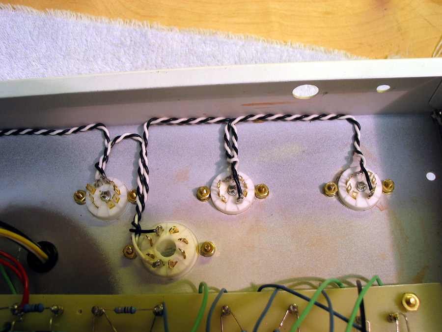
Almost Perfect: Good even twisting, right up to the sockets practically.
Secondly, the wires have been laid right into the corners to attempt to exploit the maximized shielding provided by the chassis.
This however is a secondary strategy, and must be tempered by the overall length increase created by this layout, which significantly offsets the gains from shielding.
However, this method can increase the distance of the heater wiring from sensitive components, and may payoff there if care is taken.
--------------------------------------------
(2) Almost right. However, there may be some confusion in how this method works, because of not color-coding the wires:

Here the builder has wound all the way down to the connectors. This works because the direction of flow down one wire MAY be the opposite of the flow going up to the next tube. But see conditions on the question of electrical hookup to see how this may fail!
--------------------------------
(3) Very Nice: However, it must be remembered that its not about neatness, but strictly about control of heater-field interference. Doubling a twisted pair can help smooth the field, but it can also amplify field imbalances...
Color-coding helps to keep track of the phase of the heater-lines and also the effectiveness of the twisting.
Surprising Failure: Here is a tricky example, which disguises itself as a success, but in fact is a failure in technique:
What is wrong with this picture?
The color-coding actually helps us to nail the problem.
The twisting together of two black wires for instance in the first power tube socket is a fail. Its over two inches long.
The twisting however, does NOT cancel out the current flowing into the tube heater here, which enters on the upper right and exits on the lower left.
The twist ONLY cancels out the current flowing up to the terminal and back down to the next tube's heater.
The current flowing into this power tube is NOT cancelled out,
and will produce maximum hum at the most critical area,
closest to the heater harness, the tube-socket (assuming all other parts are laid out intelligently.)
Stripped of the additional currents and circuits,
we have here an unshielded 1-inch red lead, and a 2-inch black lead, sprawled all over the socket.
The builder has not properly understood the nature of the problem.
He has only taken care of 2 out of 3 items on his layout list:
(1) Twisting the leads properly : PASS
(2) Tucking the twisted lines away: PASS
(3) Twisting/shielding the leads in the critical socket area: FAIL
(2) Tucking the twisted lines away: PASS
(3) Twisting/shielding the leads in the critical socket area: FAIL
A Second Look:
Here one ought to question the strategy of adding almost a foot of extra heater-dressing, just to run along the edge: Especially when this results in the heater running right under the input jacks!
A 4-inch run directly from socket to socket might have been better,
with components mounted an appropriate distance,
so to minimize the overall size and coverage of the heater-field.
An externally hosted image should be here but it was not working when we last tested it.
This guitar amp looks in better form than many a hi-fi layout.
Here the heater lines are isolated from chassis and all other components by distance, and the orientation of all signal lines
are at right angles to the heater.
Also, the heater is at the back of the chassis,
while the sensitive input circuits are at the front.
Given mass production assembly constraints, this is a pretty good layout.
The Electrical Layout can be as important as the physical one:
Here is a typical hookup:

Wire is rated by current-carrying capability. A lower gauge wire means a thicker one, and it is able to handle higher current.
The power tubes are placed first in the chain. This is not as most suppose, that the signal-tubes with their lower current needs are protected from the large current draw. That is not relevant. The average current and voltage will not fluctuate significantly, regardless of the order in the line.
What is being controlled here is current through the feed lines.
The more current in a wire, the more hum it can induce in other components. The high-current lines must be kept as short as possible, while the lower-current lines (for the signal tubes) can be longer and live more amiably with other components, since they produce less hum.
This usually means that the power-tubes are located closest to the power transformer, which in turn is kept away from the input section generally, along with its current-carrying lines.
Here is a typical hookup:
Wire is rated by current-carrying capability. A lower gauge wire means a thicker one, and it is able to handle higher current.
The power tubes are placed first in the chain. This is not as most suppose, that the signal-tubes with their lower current needs are protected from the large current draw. That is not relevant. The average current and voltage will not fluctuate significantly, regardless of the order in the line.
What is being controlled here is current through the feed lines.
The more current in a wire, the more hum it can induce in other components. The high-current lines must be kept as short as possible, while the lower-current lines (for the signal tubes) can be longer and live more amiably with other components, since they produce less hum.
This usually means that the power-tubes are located closest to the power transformer, which in turn is kept away from the input section generally, along with its current-carrying lines.
Final note on heater lines:
The insulation restraints can generally be lower on heater-lines, because of the low voltages (5, 6.3, 12.6). However, some runs may be held at some D.C. (direct current) voltage above ground, to prevent leakage of current to/from the cathode.
Thus a whole heater line might be floated at +100 volts or higher, to prevent both leakage and arcing on large signal swings.
Also, an amp might have two different isolated heater-lines, floating at different voltages for different tubes in different parts of a circuit (such as a SSRP or Mu-follower).
Thus one should never assume that a heater line is "only 6 or 12 volts".
It might be carrying 200 or even 500 volts D.C., and could give a lethal shock!
Thus 600volt insulation should be used for heater-lines if needed.
Other than that, the thinnest possible insulation should be used,
so that twisting can be tight as possible.
Nor should they be directly grounded to the chassis, unless it is known that they can rest at 0-volts D.C. without degradation of the sound quality or damage to tubes and/or power supplies.
If one suspects that hum on a line is generated by grounding problems from the heater-circuit, one should first try grounding it through a High Voltage small value Capacitor such as .1 uF 1Kv rating.
"The insulation restraints can generally be lower on heater-lines, because of the low voltages (5, 6.3, 12.6)."
"Thus one should never assume that a heater line is "only 6 or 12 volts".
"It might be carrying 200 or even 500 volts D.C., and could give a lethal shock!"
"Thus 600volt insulation should be used for heater-lines if needed."
Well done. I learned a little bit with this refresher course.
I should add that high voltage insulation NEEDS to be used regardless of the voltage of the heater. (5v,6.3v etc.)
You need to stop the voltage from getting into the wire, as well as out.
Often heater wires may contact with bare high voltage parts. (Regardless of neat layout or a bowl of spaghetti).
I look forward to more of your educational ramblings.
The infamous RCA / Taylor Filament theory FAIL!
In the early days, when hum was not so pressing an issue,
RCA recommended the following layout,
to alleviate current and voltage imbalances when many power tubes were hooked in series.
The idea was to run two hypothetical 'rails', connecting power to opposing ends of each.

The voltage drop caused by current imbalances in the various sections of hookup wire was balanced by the voltage drop at the other end on the other 'rail' (wire), ensuring that all tubes got the same average voltage, even if they floated up and down a little in their absolute voltage position (relative to each other) during each cycle.
Presumably the runs between each tube would be twisted as usual.
This however resulted in NO HUM Cancellation whatever!
Lets see why:

Even though the wires are twisted together, they cannot cancel,
because the current is flowing in the same direction in both wires,
at any one time.
Instead, doubling up the current just doubles the hum!
The only way this circuit could work as intended,
would be to switch to constant current D.C. voltages:
Now since there IS no hum, no cancellation is needed.
But of course no twist is needed either,
and one might as well run two physical rails.
In the early days, when hum was not so pressing an issue,
RCA recommended the following layout,
to alleviate current and voltage imbalances when many power tubes were hooked in series.
The idea was to run two hypothetical 'rails', connecting power to opposing ends of each.
The voltage drop caused by current imbalances in the various sections of hookup wire was balanced by the voltage drop at the other end on the other 'rail' (wire), ensuring that all tubes got the same average voltage, even if they floated up and down a little in their absolute voltage position (relative to each other) during each cycle.
Presumably the runs between each tube would be twisted as usual.
This however resulted in NO HUM Cancellation whatever!
Lets see why:
Even though the wires are twisted together, they cannot cancel,
because the current is flowing in the same direction in both wires,
at any one time.
Instead, doubling up the current just doubles the hum!
The only way this circuit could work as intended,
would be to switch to constant current D.C. voltages:
Now since there IS no hum, no cancellation is needed.
But of course no twist is needed either,
and one might as well run two physical rails.
oops! The following line from the last post should read:
"...to alleviate current and voltage imbalances when many power tubes were hooked in parallel."
Wire twisting will also work when tubes are connected in series, however,
care must always be taken to ensure that current not only flows in opposite directions,
but also that it is balanced in strength.
This is actually easier with series circuits, since the current is the same in every part of the circuit.
All this effort will only eliminate some of the heater-hum:
Other leaks will occur inside the tubes in the form of leakage currents between heater and cathode, unless steps are taken to float the D.C. offset voltage appropriately in relation to the D.C. on the cathode.
One way to minimize hum from heater-leakage is to use a 12.6v center-tapped winding for heaters and connect the center-tap to ground. This in theory balances the hum signal.
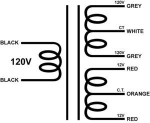
In the example below, we can see this technique:

It may be more difficult to do this with 6.3 windings that don't have a center-tap. In that case, you can make your own Center-Tap (c.t.) by using a high resistance resistor divider:
Typically, a power-amp heater circuit draws over 2 amps (.9 to 1.6 amps per tube). Ohm's Law says the heater circuit must be less than 3 ohms! We can add a divider with 1k ohm resistors (or higher) with no effect on the load at all, and connect the center to ground.
The idea here is to use as low a resistor as practical to lower random resistor-noise too.
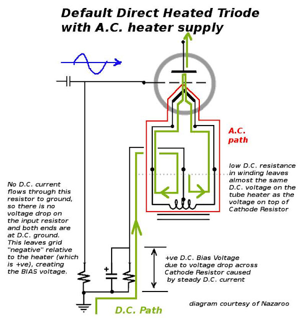
Particularly with large Directly Heated Cathode tubes (where cathode and heater are the same object), the idea is to 'balance' the hum coming from each end of the large heater/cathode (the resistance across the heater causes the voltage to differ at each end during maximum voltage swing of the heater transformer).
Below, an adjustment has been built into the circuit to minimize hum. The extra resistors ensure an approximate balance is maintained even if the pot wiper opens its circuit,
and the caps take out any transient spikes and HF noise as well.
The circuit is grounded through a resistor to prevent any current flow and/or interference with other grounded circuits.

This arrangement would work equally well with a circuit that
is floated at some D.C. value by connection to a voltage rather than ground, provided that this high-current source
cannot interact with the D.C. source in an undesirable manner.
Some designers refuse to convert A.C. to D.C. for these tubes,
because they fear uneven wear on the cathodes from chronic voltage differences
at each end of the heater inside.
But that worry can simply be alleviated with a polarity switch,
which is periodically toggled to even up the strain on the tubes.
Why have hum when you don't have to?
"...to alleviate current and voltage imbalances when many power tubes were hooked in parallel."
Wire twisting will also work when tubes are connected in series, however,
care must always be taken to ensure that current not only flows in opposite directions,
but also that it is balanced in strength.
This is actually easier with series circuits, since the current is the same in every part of the circuit.
All this effort will only eliminate some of the heater-hum:
Other leaks will occur inside the tubes in the form of leakage currents between heater and cathode, unless steps are taken to float the D.C. offset voltage appropriately in relation to the D.C. on the cathode.
One way to minimize hum from heater-leakage is to use a 12.6v center-tapped winding for heaters and connect the center-tap to ground. This in theory balances the hum signal.
In the example below, we can see this technique:
It may be more difficult to do this with 6.3 windings that don't have a center-tap. In that case, you can make your own Center-Tap (c.t.) by using a high resistance resistor divider:
Typically, a power-amp heater circuit draws over 2 amps (.9 to 1.6 amps per tube). Ohm's Law says the heater circuit must be less than 3 ohms! We can add a divider with 1k ohm resistors (or higher) with no effect on the load at all, and connect the center to ground.
The idea here is to use as low a resistor as practical to lower random resistor-noise too.
Particularly with large Directly Heated Cathode tubes (where cathode and heater are the same object), the idea is to 'balance' the hum coming from each end of the large heater/cathode (the resistance across the heater causes the voltage to differ at each end during maximum voltage swing of the heater transformer).
Below, an adjustment has been built into the circuit to minimize hum. The extra resistors ensure an approximate balance is maintained even if the pot wiper opens its circuit,
and the caps take out any transient spikes and HF noise as well.
The circuit is grounded through a resistor to prevent any current flow and/or interference with other grounded circuits.
This arrangement would work equally well with a circuit that
is floated at some D.C. value by connection to a voltage rather than ground, provided that this high-current source
cannot interact with the D.C. source in an undesirable manner.
Some designers refuse to convert A.C. to D.C. for these tubes,
because they fear uneven wear on the cathodes from chronic voltage differences
at each end of the heater inside.
But that worry can simply be alleviated with a polarity switch,
which is periodically toggled to even up the strain on the tubes.
Why have hum when you don't have to?
Last edited:
The picture here for illustration was taken from a motor wiring page...so maybe for their purposes 6 turns per foot was adequate to prevent bleeding of servo-motor signals into motor power line...Altough I count in meters, I think it meant to say per inch
 I thought this thread was worthy of being made a sticky - lots of really good filament wiring information here. Several fellow mods agreed. This is an area where a lot of newbies, and not so new(bies) get into trouble. 😀
this is a very good post.
thank you very much for this useful information!
a little question,
if i convert the heater supply to d.c, it should eliminate the RF antenna effect?
thank you very much for this useful information!
a little question,
if i convert the heater supply to d.c, it should eliminate the RF antenna effect?
Altough I count in meters, I think it meant to say per inch
I don't think so. All vintage wire and some modern wire can't be twisted 6 times per inch then subjected to thermal stress. Teflon is an obvious exception but even the stranded copper wire will object to such a tight twist. The smaller the gauge, the tighter it can be twisted.
I tend to twist the wire tighter for short runs and about 1 to 2 twists per inch maximum for longer runs.
Some of what is accepted practice in the tube audio world is in direct conflict with some of the concepts I have learned in 40 years of building two way radio equipment for extreme duty applications.
If you are building a box that sits on a shelf for years at a time and rarely gets moved, you can get away with long twisted runs and components suspended by their leads only.
If you are building a box that goes in the trunk of a black cop car in Arizona or Minnesota in January, or the dash of a Hummer in the desert, or filled full of hot tubes sitting on the top of a stack of speakers on a stage, you can't.
this is a very good post.
thank you very much for this useful information!
a little question,
if i convert the heater supply to d.c, it should eliminate the RF antenna effect?
Great question.
A power supply regulator and caps cannot stop an antenna arrangement from being one. But it will block and absorb transmission and effectively completely alter and destroy the function of it.
Any 'antenna' effects still coming in on the heater lines would have to enter through the open bottom (or top) of a 3/4 closure like a guitar amp chassis. The final cure is to install a finishing plate, which should have been provided by the maker.
Really helpful, thank you!
Can you explain how the typical cathode bias resistor of a DHT would interact with the hum-balancing network in the "Power Supply for a large direct-heated triode"?
Would the (usually capacitor bypassed) cathode bias resistor simply go from the junction of the two .002uF capacitors to ground, effectively floating the whole filament secondary?
Or would one use a center-tapped secondary and attach the cathode bias resistor in series with the center tap to ground, in the usual way? Wouldn't that bypass this hum-cancelling network too?
I'm probably missing something that's obvious to most...
--
Lets have a look at your 'typical' circuit (I'm using your description here):
The design suffers from a few potential problems:
(1) The Winding of the transformer and its total reactance (AC/DC) should be closely balanced. If it isn't there is no obvious adjustment to fix this as it stands.
(2) The wear in the tube should be even along with emission currents from both ends of the heater element. Typically however, tube emission varies unpredictably over the tube-life.
(3) There should be no current through the grid, and the resistance path to ground should be relatively low, to keep the bias stable and well-defined.
Now lets talk about why the circuit cannot deliver:
(1) The winding for a heater-transformer will not be wound the way a Push-Pull Output xformer is. In those, the windings and current must be balanced, to cancel the magnetization and core-saturation. A typical heater winding is a single coil, not a bifilar winding, and so, balancing it has no meaning in regard to D.C. flow. It WILL ALWAYS magnetize the transformer core, and use up precious core-flux. That is why it is better for the other windings to leave unneeded windings unused. Nothing is free.
The only issue then is to balance the D.C. flow for the purpose of even wear on the cathode emitter. But this also will fluctuate with tube-wear and is uncontrollable from outside of the tube. At best, you can have a compensating circuit which monitors D.C. idle current through both terminals, and adjusts itself.
(2) There is a real danger here that any attempts at adjustment of current-flow will exascerbate tube element wear unevenness (and also applied voltage). I leave that to your imagination.
(3) In many cases, Direct-Heated Triodes have relatively low Bias-points, and conduct some grid current during a cycle. In this case, Cathode-Bias technique may be less stable than desired.
Last edited:
Thanks, this is great stuff!
OK, so I can only think of two relatively simple solutions to propose.
1) DC filament supply, or
2) Fixed bias
_______________________________________
Could one heat the e.g. 6.3V filament with a well-filtered or regulated +3.15V and -3.15V supply? Would having the voltages fixed be at least a partial solution, allowing cathode bias to work better?
Or would regulating the current drawn by the filament (say at 1A for a 6B4G, for instance) be a better solution?
--
I should warn you that I'm at the limit of my understanding here. Thanks for the great drawings, they help a lot. Do you teach by any chance?
OK, so I can only think of two relatively simple solutions to propose.
1) DC filament supply, or
2) Fixed bias
_______________________________________
The only issue then is to balance the D.C. flow for the purpose of even wear on the cathode emitter.
Could one heat the e.g. 6.3V filament with a well-filtered or regulated +3.15V and -3.15V supply? Would having the voltages fixed be at least a partial solution, allowing cathode bias to work better?
Or would regulating the current drawn by the filament (say at 1A for a 6B4G, for instance) be a better solution?
--
I should warn you that I'm at the limit of my understanding here. Thanks for the great drawings, they help a lot. Do you teach by any chance?
Fixed bias and DC filament supplies are always a good idea with DHTs, just make sure that the filament supply is very well filtered - there is nothing worse sounding than a touch of 120Hz sawtooth in the filament DC.
AC DHT heating also adds intermodulation distortion products at multiples of the line frequency between the heating supply and the audio you are trying to amplifier. George (tubelab) has commented on this in the past.
My experience in dht power amplifiers is that anything over 2.5V is best DC heated to avoid buzz issues, and the IMD issue mentioned previously.
Constant current heating of dht filaments is pretty near ideal IMLE, controlled warm up limiting inrush current to the rated design current of the filament should be good for filament life, and the rejection of noise on the filament supply is usually quite good. (10yrs of using CCS for filament heating and I have never had a filament failure in that time. Previous to this they were rare but did happen.) In addition with some topologies the filament raw power supply can be completely excluded from the audio path.
- Home
- Amplifiers
- Tubes / Valves
- Heater Wiring - the Good the Bad and the Ugly