Hi,
Appreciated your input. I was not thinking about RF getting into the Driver tube, but I was thinking about snubbing all those nasty fields, inherent in the power transformer, and radiated from the power transformer itself, into the filament winding.
I am not sure what the fields from the two 500 uHY chokes will do, when in proximity to the tube socket, and all that low level signals present on the grid of the input tube, etc etc.
Granted, what I propose is NOT the normal way of executing the filaments. Its new. If ANYONE has any ideas on this, I would welcome input, and their thoughts. Don't hold back !!
Thanks so much !!
Jeff
An RF choke is as likely to pick up a magnetic field as it is to stop a current from flowing. It will, of course, increase magnetic coupling (in both directions) between the heater wiring and other circuit loops.
"Snubbing" is not a word I would use for a low pass filter. The power transformer does not "radiate" any fields, as it is far too small for radiation to take place.
I fear you are proposing an inappropriate 'solution' to a non-problem. That may be why it appears to be "new". Good AC heater wiring practice is the thing to go for; very old, but it works.
Appreciated your input. I was not thinking about RF getting into the Driver tube, but I was thinking about snubbing all those nasty fields, inherent in the power transformer, and radiated from the power transformer itself, into the filament winding.
A choke of the type that you refer to will not help reduce common mode noise (data here). If there is any common mode noise from the supply (perhaps from some HF coupling from primary to secondary windings rather than through the magnetics) then a bifilar wound choke would be more suitable. Differential noise across the filament will be pretty unlikely in most cases and at the frequencies that this choke would block the noise would not be coming from the transformer in any case.
If hash getting on to the filament wiring is really a concern, then perhaps some simple decoupling either across the filament supply and from the filament supply to the chassis would be rather more effective (and a lot cheaper).
Also, are you looking at this in relation to directly heated or indirectly heated cathodes? In indirectly heated tubes the layout of the filament helps to prevent differential noise coupling to the cathode. With directly heated cathodes the problems are more to do with either hum cancellation if AC driven, or suitable voltage or current regulation if DC driven.
However, I am with DF96 on this. This really shouldn't be a problem if care is taken over the wiring layout as described previously in this thread.
I do like inductors on DHT cathode circuits. for some reason I like its character it imparts.
I treat indirect heated tubes different depending on the situation.
as far as DrLowmu's issue, I would have to see an o-scope picture to determine the origin and determine the correct methodology to apply to the circuit.
I treat indirect heated tubes different depending on the situation.
as far as DrLowmu's issue, I would have to see an o-scope picture to determine the origin and determine the correct methodology to apply to the circuit.
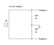
Morgan Jones talks of using an RF common mode choke in the feed to heaters, followed by balanced capacitors to chassis to, I presume reduce electrostatically coupled noise via the cathode.How about using a RF Hash Choke right at the filament pins on the tube socket ?
Small chokes are often used as a series addition to larger inductors to improve their parasitic characteristics, extending bandwith, and inductors have been successfully used with filaments to separate signal from supply albeit a less practical way to do things.
Hi gang!
I'm working on laying out my 1st amp and I'm in the process of bathing parts and laying things out with Adobe Illustrator. I'm building a Chubby Clementine amp with point to point construction KT88 power tubes and 6SN7 pre tube. See below for the heater circuit off the 6.3V secondaries.
Here are a few questions for the heater wires:
1) what brand / type / gauge of solid wire?
2) what order should I run the wires to the tubes? Should I tie into the 2 power tubes first, or start at the pre tube?
3) what would be your preference for the two colors I should use?
Thanks! This thread has been very informative!
Attachments

Solid insulated copper wire of the right thickness to carry the current while under a hot chassis is what you need. For 3A of heater current I used cores from 20A mains cable. Ignore brand. Twist the wire tightly - there is lots of information online about how to do AC heater wiring. Do power valves first, so there is not too much AC current near the small signal section. You can use thinner wire for the smaller valves.
My cables happened to be red and black, but colour does not matter. It should be obvious which is the heater wiring, and AC does not need to show polarity.
My cables happened to be red and black, but colour does not matter. It should be obvious which is the heater wiring, and AC does not need to show polarity.
Best way that I have found to keep heaters hum free is a nice tight twist, and tucking everything around sockets, and hugging corners away from other components... make "drops" from the edge of the chassis to the tube sockets, taking care to only cross other signal wiring at 90° (perpendicular) angles. Lifting the heater reference from ground up to a higher voltage (as you would when working with a concertina splitter or cathode follower anyway) can further help. Solid core wire is handy for keeping everything tucked away without glue or cable tie wraps. I have such consistent success that I don't bother with DC heaters on anything that doesn't have a SMPS anymore, or the occasional instance where series DC heating would be more logistically convenient (like when you already have ±12~15 volt rails for clamps or similar circuitry) or easier to implement.
Hi today I have redone the twisting of the preamp just to be sure.
I twisted well, did not curve the wires around the socket, tucked the wires in the side of the chassis but no improvement over the straight wires placed side by side. And it's a hi gain 3 gainstages design.
Is it a myth or can you explain the physics behind this practice ?
I have read the whole thread but can 't make sense of it. But I understand that two opposite magnetic field cancel each other when they are close.
But still why twisting is better ? as it will not make the wires any closer.
Twisting ensure that the wires stay as close as possible. This reduces the external electric field, provided that the wire voltages are balanced around ground.
Putting heater wiring into the corner of a metal chassis works because even putting a grounded conductor behind something reduces the electric field in front of it. This may seem counter intuitive. One way to think about this is that the wire has electric field lines coming from it. Every one of these must terminate somewhere else. They prefer to keep short and straight, and to end up somewhere of the opposite potential when possible. They can bend, though, so if you put a grounded conductor just behind the wire then many of them will just bend around and land there, leaving fewer to go off searching for somewhere else to land (such as your input grid wiring).
Putting heater wiring into the corner of a metal chassis works because even putting a grounded conductor behind something reduces the electric field in front of it. This may seem counter intuitive. One way to think about this is that the wire has electric field lines coming from it. Every one of these must terminate somewhere else. They prefer to keep short and straight, and to end up somewhere of the opposite potential when possible. They can bend, though, so if you put a grounded conductor just behind the wire then many of them will just bend around and land there, leaving fewer to go off searching for somewhere else to land (such as your input grid wiring).
- Home
- Amplifiers
- Tubes / Valves
- Heater Wiring - the Good the Bad and the Ugly