Thanks for putting this together, it has helped me, I have switched from mains power to Standalone solar power 24vdc/220vac 50hz pure sine wave inverter and my valve amp now seems to be running prefect, as I now run 85% of my home on Standalone solar. I could run my heaters on the valve amp directly off battery power with a regulator reg the power at a constant 6.3v but it is easier now just to plug it into the pure sine wave inverter. You wrote on my post and it helped me I got confused on 1 thing but Am working that out {I think lol}
Hi Guido and valve 5425 and others thanks
Very interesting tread and answers.
I will go with a séparate filament transformer with center tap and try also some dc way.
I must say that I like old ways for tube amplifiers.
But an open mind is alwalys the best way.
Gilles from France, a rainy day in Normandy.")
Very interesting tread and answers.
I will go with a séparate filament transformer with center tap and try also some dc way.
I must say that I like old ways for tube amplifiers.
But an open mind is alwalys the best way.
Gilles from France, a rainy day in Normandy.
Cat5 pairs for heater wiring came up in another thread. The longest twist pitch on one of the pairs may be too long for AC heaters. Note that Cat5 gains its isolation not from tight twisting but from different twisting in each pair. It is solving a different problem: inter-pair crosstalk rather than interaction with nearby circuits.
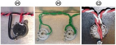
Here is something I did, it might help. The picture is not so good but you can see some of the copper the showing. They sell this kind of copy foil with conductive adhesive for electrical shielding. It is tough tape, almost like duct tape.
After doing the hearer wire I covered it over with copper tape. I did it all correctly, run in the corners and so on but then as an extra I cover it all in copper. This does 3 things (1) it looks cool and hides the wire and (2) it sticks the wires down and keeps them in place and maybe (3) it adds small amount of shielding.
Heater wires creat a magnetic field mostly and copper does not much for that but it might keep radio and what not out. And it looks good
https://www.dropbox.com/s/vhj9ykofaodw936/guts.jpg?dl=0
The amp BTW is a modernized clone of a Fender Champ. I used Fenders 50's vintage schematics but modern construction techniques and it is dead quiet with a very low noise floor. It uses a power supply choke and some slightly over sized filter caps and is wired with brightly colored coaxial shielded hookup wire with shields grounded at one end. The heaters are AC but running at 5.8 volts and the AC is biased up to about 1/10th of B+. This I find makes it run quiet.
Seeing as this thread is about heater wire I'll re-state the point of running at 5.8 volts. It is inside the allied spec of 6.3V +/- 10%. Running at the low end of the allowed range makes the tubes last nearly forever and put less current in the wires. I drop the volts with a large 25W resister in series with the transformer. Then I build a voltage diver so get about 20VDC and attach that to the heater loop also
Using coax wire and keeping the sheild on all the way to the tube sock pin keeps "hum" out of the signal
The Champ is a 6V6 power single ended amp. That is an ALNICO magnet speaker.
Last edited:
How does the modern treatment affect the character of the end result?
I worried about that a little. I tried not to change what I thought might matter. All the component values are the same, or really they are a cross between the first two versions of the Fender Champ. I think it is the circuit topology and component values and especially the choice of which output transformer to use that matters.
I changed these things:
1) Fender user the chassis for the return current from the heaters. They ran a 6.3 volt "hot" AC wire to each tune then connected the tube socket's other heater pin to the steel chassis. They use a short bare wire to jumper the socket pin to the chassis. I was actually surprised to see that solder would stick to a chromed steel chassis.
2) Fender also used the steel chassis for signal ground too. They soldered direct to the chassis.
3) Fender used cloth covered solid hookup wires in the signal path. I used shielded wire for all wires that connect to a tube's grid. I did not want those wires picking up "what ever".
4) Fender close of the 6th side of the chassis with a plywood panel. I though this was a fire hazard and also wanted more electrical noise shielding. I laminated an aluminum sheet to the inside of the plywood cover and adjusted for good mechanical fit.
5) added hum balance resister network to heaters, connected this to a roughly 20vdc bias made from a voltage divider off the B+. Used about 10f cap on this bias to ensure 0vac bias. This makes the current in both legs of the twisted pair equal and average about 20 or 30 volts above ground. I also placed a low value (maybe 0.5 ohm?) in series to reduce heater voltage.
6) later version of the champ eliminated the choke on the power supply, I let it in. I also used the larger filter caps in the seconder Cham version. I might have a stiffer power supply?
Power supply "stiffness" does effect the sound of a push-pull amplifier. This is because a PP amp's demand on power depends on how loud the sound is. The PP amp uses more current from the power transformer to make louder sounds. But a single end class A amp uses the most current when the input is shorted to ground. So,... A PP amp with a weak power supply compresses the music. It make the dynamic range smaller. This is normally a Good Thing. So MANY PP amps intentional are under powered. But there is no such effect with a Class A amp. So bottom line is I doubt my choke and slightly larger filter caps effect the sound. My ears say they don't. Well except to greatly reduce the hum and buzz.
I think NOT using the steel chassis for heater current return and going with a STAR ground for the signal ground very much reduces the noise floor as well.
This amp sounds like a Champ but with reduced noise floor.
The noise is almost 100% from the guitar. But I've added 100% full copper shielding to all the routed cavities. The copper foil is soldered to a drain wire that connect at the 1/4" output jack. This allows me to play near a computer and under many CFL lights. It s not 100% effective, more like 80%
This hum from guitar circuit can be reduced too
The problem is that all metal plates carrying the elements, pots, switches and jacks in some,
have thin layer of nickel or other shining stuf.
with the years this layer is not too tight to the metal plate and there is some oxidation in the
space between. As the grounds are usually soldered at the pots chassis, via mechanical contacts they are summed "together". With this layer of nickel...
.
I desoldered all grounds from pots, make one solid ground point and soldered in that point all, added a good health point from the plate.
At my telecaster bigsby, and other telecaster standard hum was gone, and everything was much clear then before
wire gauge
Hi,
Concerning wire gauge per heater current requirements (hope this thread is appropriate)...
I referenced the American Wire Gauge tables but wondering if more conservate measures should be made. For instance, my application is for a 3A filament. I'm in breadboard mode and just used the stranded 20 awg wire I had at my disposal. Single 20 awg has a max rating of 11A but questioning if I should be using more like 16 awg.
Any rule of thumb for gauge per current?
I am planning to use 20 awg (0.8mm diameter) solid core, 900V rated wire for supplying my EL34 heaters. This means 1.5A per wire - I will run two twists to ease things up thermally.
In free air, I passed 3A through one twisted pair of the above wire for about half an hour+, and did not feel any temperature difference.
Do you think it is sufficient for long term reliability? Having read many specs around the internet, and even Jones' rule of thumb that a 0.6mm pvc conductor can take 1.5A max, I think it is sufficient for the job. But you may have had other experience!
this helps
The Valve Wizard
The Valve Wizard
Attachments
Last edited:
 Off topic input capacitor posts will be moved to a new thread. Can we please keep posts on topic?
Edit: They have been relocated to a new thread here: http://www.diyaudio.com/forums/tube...m-changing-1st-condenser-vc508-schematic.html
This topic is about heater wiring and implementing good practices during builds.
Hi all,
I'm having a pretty weird issue with my 6SN7 heaters in my stereo amp. The issue was present with both AC and DC heaters but disappeared with a 6V battery as the heater supply. Both heaters are connected to the same supply, parallel, not in series. I've also tried several sets of 6SN7s in various stages of life and quality. Brand new and really old. All of them have the same issue. I'm having exactly 6.3V AC from a dedicated toroidal transformer on the heaters right now.
My heaters were floating (no ground reference) and there was an audible buzz. With the battery there was no buzz at all. I tried rewiring, measured all the voltages and I just simply couldn't find anything wrong anywhere. I made an artificial center tap using two 100Ω resistors, but the buzz just got worse.
Out of desperation I just put an alligator clip test lead to one of the heater pins on the tube socket, and connected the other end to star ground. The hum disappeared at first but within a few seconds it got really bad. I made a permanent connection with a ground wire soldered in place, and the buzz was back, worse than ever before. As soon as I clipped the ground wire, the buzz was reduced, but it was still very much audible. I didn't know what to do, so again I put the test lead to the heater pin on the tube socket, and tried grounding it in different spots of the chassis. No change. Every time I connected the lead to ground, the buzz got gradually worse. Then I decided to connect it to the cathode. Buzz disappears completely. So here I am, with a quiet amp, not really understanding why this happened.
The real question is whether this is safe or not? Is it OK to have one end of the heater connected to the cathode (pin 3) on just one of the 6SN7s?
.....My heaters were floating (no ground reference)......
.....Then I decided to connect it to the cathode. Buzz disappears completely...
Floating as in isolated from the rest of the circuit or elevated? What you're doing with connecting it to the cathode of one of the tubes is a very common way of elevating your heater ground. Previously when you had it "floating" did you have it elevated via a CT or a virtual CT with a reference voltage? If not its possible that you were exceeding the 100 Vh-k limit which was causing migration and undue noise.
afaik you should be perfectly safe with it as-is, I've never used the cathode tie method however so maybe one of the others can chime in.
this helps
The Valve Wizard
I would highly recommend the rest of the Valve Wizard's web site and his books. Particularly if your interest is valve guitar amplifiers.
Cheers
Floating as in isolated from the rest of the circuit or elevated?
As in the transformer winding was only connected to the heater pins, so isolated from everything else. A bad idea, I know.
What you're doing with connecting it to the cathode of one of the tubes is a very common way of elevating your heater ground. Previously when you had it "floating" did you have it elevated via a CT or a virtual CT with a reference voltage? If not its possible that you were exceeding the 100 Vh-k limit which was causing migration and undue noise.
OK, I think I got the information that I needed, many thanks for that. I just wasn't sure if it's OK to reference the heater winding to the cathode. From the information that I gathered on the forum, I was suspecting that the exceeding of the Vh-k might be the cause for the buzz. I've been blasting the amp for a few days now, and no problems so far.
afaik you should be perfectly safe with it as-is, I've never used the cathode tie method however so maybe one of the others can chime in.
Sure, any expert views are more than welcome.
The real question is whether this is safe or not? Is it OK to have one end of the heater connected to the cathode (pin 3) on just one of the 6SN7s?
no....this is how i do it in my amps...
r1 and r2 sized to give around 50volts, r3 and r4 can be 470 ohms...
c1 can be 470ufd/63 volts....
this one from the valvewizard site:
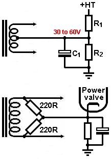
Yes. The heater supply must always have a DC reference. Ground is often good, but a somewhat elevated DC voltage can be better. The cathode of an output stage can be used; the cathode of an input stage may increase hum.vuohi said:The real question is whether this is safe or not? Is it OK to have one end of the heater connected to the cathode (pin 3) on just one of the 6SN7s?
However, it would be good to know what caused the buzz. Strange buzz/hum problems are often a symptom of parasitic oscillation.
Last edited:
no....this is how i do it in my amps...
r1 and r2 sized to give around 50volts, r3 and r4 can be 470 ohms...
c1 can be 470ufd/63 volts....
this one from the valvewizard site:
nice to hear ya tony
you've been doing this genius technique long before we found this
- Home
- Amplifiers
- Tubes / Valves
- Heater Wiring - the Good the Bad and the Ugly