Hello,
@Chris
there is LF Oscillation and the squeeging with the feedback loop open,
there is LF Oscillation as soon as i feed a signal <40Hz from the pc to the amp. it's visible at the bias balance leds.
Initially I was thinking of accusing the LF sub oscillation at an overvalued interstage coupling cap (C46? 0.47uF) but you having mentioned LF oscillation with the global feedback loop open, that prettywell rules that out. Now I'm becoming suspicious of a dirty signal source from a pc.
It may have alot of RF i.e badly filtered but maybe well above the 1st stage zobel R/C pole.
richy
Tom, Pardon me, I don't mean to be offensive.
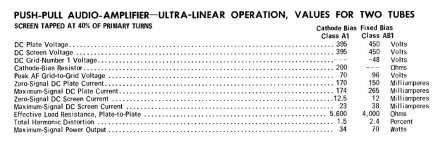
But I am still perturbed to find my suspicions are founded - some portion of a DataSheet 101 is really required. I can see that the Simulator has lulled you into thinking that the data sheet values for Ia+Ig2 are peak values, when in fact they are always dc or average values. This is true for old UK data sheets (The Symbol I is defined as dc current in a data-sheet British Standard of the time), and U.S. originated ones as well. It is true for an 813 transmitting tube, just as it is an Audio Beam tube.
There's no need for me to prove this by dragging out the measurements for the my old KT88 amp - it can be demonstrated in minutes using traditional graphical analysis. It is very easy in this case because our KT88 amp is run in text book operating conditions.
As per KT88 data sheet, we use:
Va(0) = 453V
Ia+g2(0) = 2x 50mA
Ia+g2(max sig)= 2x 140mA
RL A-A = 4K
bias = -59V
Vg1 (ac)(crest)=114V (ie peak to peak)
Pout = 70W
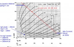
Textbook UL conditions are used, so a load line can be imposed on the UL curves given in the data sheet.
Construct the load line in the usual way. For PP, we analyse a single valve's curve. Each PP half drives half the voltage, so the impedance presented to a single valve is 4K/(N^2) = 4K/4 = 1K. We draw the load line from the bias point (453V, 50mA), and take a 1K gradient to the point where Vg1 = -2V: i.e.: (-59 + 114/2)V.
Read off the peak currents: Ia = 360mA peak, Ig2 = 36mA peak.
Therefore,
Ia+Ig2 peak = 396mA
I(av) = I peak / (2^0.5) = 280mA
The B+ capacitor carries out the peak-to-average conversion: that is exactly what it is there for. Therefore, the dc supply current becomes the data-sheet value of 280mA dc.
I would never be parted from my SPICE simulator, and use it every day for professional purposes. For quantification, and experimentation with values and choices, it save me so much time. But I never use it to tell me how something works... I will always work out a circuit by hand first. The day one stops doing this, one risks losing control over one's designs....
But I am still perturbed to find my suspicions are founded - some portion of a DataSheet 101 is really required. I can see that the Simulator has lulled you into thinking that the data sheet values for Ia+Ig2 are peak values, when in fact they are always dc or average values. This is true for old UK data sheets (The Symbol I is defined as dc current in a data-sheet British Standard of the time), and U.S. originated ones as well. It is true for an 813 transmitting tube, just as it is an Audio Beam tube.
There's no need for me to prove this by dragging out the measurements for the my old KT88 amp - it can be demonstrated in minutes using traditional graphical analysis. It is very easy in this case because our KT88 amp is run in text book operating conditions.
As per KT88 data sheet, we use:
Va(0) = 453V
Ia+g2(0) = 2x 50mA
Ia+g2(max sig)= 2x 140mA
RL A-A = 4K
bias = -59V
Vg1 (ac)(crest)=114V (ie peak to peak)
Pout = 70W
Textbook UL conditions are used, so a load line can be imposed on the UL curves given in the data sheet.
Construct the load line in the usual way. For PP, we analyse a single valve's curve. Each PP half drives half the voltage, so the impedance presented to a single valve is 4K/(N^2) = 4K/4 = 1K. We draw the load line from the bias point (453V, 50mA), and take a 1K gradient to the point where Vg1 = -2V: i.e.: (-59 + 114/2)V.
Read off the peak currents: Ia = 360mA peak, Ig2 = 36mA peak.
Therefore,
Ia+Ig2 peak = 396mA
I(av) = I peak / (2^0.5) = 280mA
The B+ capacitor carries out the peak-to-average conversion: that is exactly what it is there for. Therefore, the dc supply current becomes the data-sheet value of 280mA dc.
I would never be parted from my SPICE simulator, and use it every day for professional purposes. For quantification, and experimentation with values and choices, it save me so much time. But I never use it to tell me how something works... I will always work out a circuit by hand first. The day one stops doing this, one risks losing control over one's designs....
Attachments
Last edited:
Read off the peak currents: Ia = 360mA peak, Ig2 = 36mA peak.
I agree.
So why does my simulation line up so well with the datasheet values? Happy coincidence? Did I somehow get off by exactly sqrt(2)?
The B+ capacitor carries out the peak-to-average conversion: that is exactly what it is there for. Therefore, the dc supply current becomes the data-sheet value of 280mA dc.
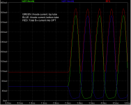
How does a capacitor average current? Given that the reservoir cap is constantly recharged, I can see how it would average the B+ voltage, but not the current...
The inductance of the OPT primary winding, on the other hand would do a fine job of averaging the current. Naturally, this would lead to a change in the waveform shape from the full-wave rectified waveform you described earlier to something with a lower di/dt.
But I never use it to tell me how something works... I will always work out a circuit by hand first. The day one stops doing this, one risks losing control over one's designs....
I use simulation tools to assist me in the learning process. I use that along with graphical methods like load line analysis, etc. for my designs. And I do appreciate you taking the time to draw up that load line. I hadn't taken the time to do that. Thanks.
There are many ways to accomplish one's goals. I hope the Internet is big enough to allow us to coexist despite any differences in our design or learning approaches.
~Tom
Rod,
I took the parasitic resistance out of the OPT model. Now, I'm able to reproduce the datasheet values as you describe. I guess the sqrt(2) difference was just pure coincidence.
I think I misunderstood your comment about the B+ capacitor averaging the current. I took "averaging" to mean "smoothing". My bad. The current isn't changed by the capacitor, but the voltage across the capacitor is proportional to the integral (or "average") of the current into (or out of) it.
I think we agree now. Thanks for the discussion. Yurgs - sorry we polluted your thread.
~Tom
Attachments
Tom, Great. Agree, plenty of room for many approaches.
While we have the UL load line to hand, may as well examine the effect of the apparent mismatch. As you say, connecting 8R to the secondary of an OT intended to go from 5K to 3.85R - will present over 10K to the Anodes.
This load reduces the peak anode current to 200mA or so, and the dc Ia+g2 drops to about 155mA per channel.
This could well explain why Yurgs is seeing only a small drop in the dc supply, when clipping takes place.
4R load (eg 2x parallel 8R) certainly recommended, Yurgs!
Attachments
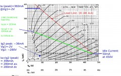
The other risk with that high load - the load-line hits Vg1=0 below the knee in the curves. This means that the peak Ig2 can suddenly increase as Va drops below about 60V, and reach damaging levels.
The G2 stoppers are there to keep this effect from getting out of control - but still, operating with such a light load is a risk. Overheated screens are the top killer for End-tubes.
The G2 stoppers are there to keep this effect from getting out of control - but still, operating with such a light load is a risk. Overheated screens are the top killer for End-tubes.
Initially I was thinking of accusing the LF sub oscillation at an overvalued interstage coupling cap (C46? 0.47uF) but you having mentioned LF oscillation with the global feedback loop open, that prettywell rules that out. Now I'm becoming suspicious of a dirty signal source from a pc.
It may have alot of RF i.e badly filtered but maybe well above the 1st stage zobel R/C pole.
Yeah... I'm not convinced the problem is in the amp, actually.
- We've beaten the supply concerns to death. Yeah, it's not an ideal design, but it doesn't seem to be significantly worse than most other stuff out there.
- The amp shows the same signs of misbehaving when the global negative feedback loop is open. So it's not a loop stability issue.
- While the CCS'es do eat up a good 50 V of headroom (at least the one in the input stage does) and could be improved, there is really nothing downright wrong with them.
Yurgs stated that the problem started at f < 40 Hz when the input was turned up. How high does the volume need to be turned up in order for the problem to be present? I.e. what's the output power into a 4R load when the problem is present?
~Tom
The schematic in Post #2 says 5k:3.85ohm for the OPT. I interpret this as a 5k primary when loaded by 3.85 ohm on the secondary. If this is correct, then I suggest using a 3.9 ohm or 4 ohm dummy load. If an 8 ohm load is used, the primary impedance will be closer to 10 kOhm, resulting in lower output power.
~Tom
tom , this is correct, the opt offers a variety of load matching options, i initialy set it up that way thinking that a 10k load is easier to drive than a 8k load, and i could run the amp on this setting for 4 and 8r speakers. i also asumed that most speakers average on something like 6r anyway.
i am away for work reasons for the whole week, and therefore not able to change or measure anything
i can try with a 4r load on the weekend if everything here at work runs smoothly.
@rob & tom, seeing that it helps me understanding some basics of psu design,
no, i dont mind these things beeing discussed here, as long as it sort of helps the idea of the original thread.
i also wanted to add that i use KT90 in the amp now.
Chris mentioned earlier that he would focus on getting rid of parasitic oscillation first( Morgan Jones as well), the only thing i tried in this direction is replacing the gridstoppers on the output tubes with 10k, but with no change.
the noise i called squeeging might in fact be something else, i believe its produced by the right output tube of the chanel under test. ( because it sounds different when i touch the envelope of the tube with my fingernail)
so maybe this is connected to the load - matching of the opt as well.
i initialy set it up that way thinking that a 10k load is easier to drive than a 8k load, and i could run the amp on this setting for 4 and 8r speakers. i also asumed that most speakers average on something like 6r anyway.
I would recommend running the amp at its specified load impedance. Though, you're right. Most speakers' impedance vary widely across frequency.
~Tom
I took a closer look to the schematic. IMHO there are some oddities, both on original from
Integrated5050
and the one modified and built by yurgs.
1) What is the reason of paralleling 2 triodes of the input pre-driver? I see none whatsoever. Additionally, in the original amp pre-driver have 2.5mA anode current, and yurgs' - 5mA (according to his schematic, 10mA / 2 = 5 mA).
2) Paralleling triodes in LTP - another unnecessary complexity.
3) CCS (constant current sink, MJE340) in LTP - really odd connection. Tail of the LTP doesn't seem to be connected to the ground anywhere. Emitter of MJE340 must be grounded, instead, it is connected to -87V BIAS supply. I think this is an error on the drawing (from Turneraudio).
post 89 Yurg
Don't go spending into KT90's if the amp is not behaving properly; Currently your amp isn't stable. With these highish gm tubes, UL screen taps to anode R/C's is a must otherwise one can do damage.
Once stable, with KT90's fitted, expect around 20% more output power compared to KT88's. EH KT90's like more current on the UL screens and perform best with a lowish imped G1 drive. If one is after long life then OK; 475V is an easy voltage for these tubes.
richy
The circuit seems perfectly OK to me. If the CCS was returned to ground then there would be very little voltage developed across it to ensure correct operation, and the other input (currently -24V) would of course need to be changed.3) CCS (constant current sink, MJE340) in LTP - really odd connection. Tail of the LTP doesn't seem to be connected to the ground anywhere. Emitter of MJE340 must be grounded, instead, it is connected to -87V BIAS supply. I think this is an error on the drawing (from Turneraudio).
The current sink as drawn will work fine so long as the -87V and -24V rails are clean and the two rails are referenced to the signal ground (not to chassis). The current level is of course defined by the voltage developed across the 5.3K resistor (about 62 volts) which results in 11.7mA (hence nominally 6mA either side of the LTP).
Last edited:
I took a closer look to the schematic. IMHO there
1) What is the reason of paralleling 2 triodes of the input pre-driver? I see none whatsoever. Additionally, in the original amp pre-driver have 2.5mA anode current, and yurgs' - 5mA (according to his schematic, 10mA / 2 = 5 mA).
2) Paralleling triodes in LTP - another unnecessary complexity.
3) CCS (constant current sink, MJE340) in LTP - really odd connection. .
1.the main reason is to reduce noise, the original circuit runs 6cg7 and in my amp its 5814A, which have less gain. therefore are set at 5mA each.
3. Works fine, at least in regards to current.
@Richy, i never had anything else than KT90s and they were cheap when i bought them a while ago..
Once (a long time ago) I paralleled some valves and forgot to use grid stopper resistors. The amplifier was an instant motorboat... bububububububububub!
Addition of 300 to 1k Ohm grid stoppers on the paralleled sections fixed it immediately.
Look at V3 and V4 in the schematic posted just recently.
Ian
Addition of 300 to 1k Ohm grid stoppers on the paralleled sections fixed it immediately.
Look at V3 and V4 in the schematic posted just recently.
Ian
Hey there, sorry for the time it takes to get back to you guys.
I am away from home for work reasons, and that will unfortunately take until the end of July. so no amp work for me :-( i managed to get the parts for my blown sound card interface, at least i am able to measure again.
i will test with a 4ohm load first and then try the gridstoppers,
yurgs
I am away from home for work reasons, and that will unfortunately take until the end of July. so no amp work for me :-( i managed to get the parts for my blown sound card interface, at least i am able to measure again.
i will test with a 4ohm load first and then try the gridstoppers,
yurgs
hey there.
sometimes life gets in the way of things....
I was not able to put much time towards the amp project, but i should be able to deal with things now.
1. i changed the load to 4r, with no change in the squeeging.
2. i took out the ccs on v1 and v2, and used resistive anode-loads and i replaced the 5814 with e12AU7,
so the circuit is basically as it was designed originally, the problems stayed the same though.
3. i checked the source,
the cleanest source i have is a pc with a soundcard 192khz
pic 7496 shows two traces of 10kHz, top=source, bottom= ampoutput at 1W
pic 7497 shows the same @ Timebase 10uS
the spikes on the top trace must be the 192kHz, and the botom trace shows the "swinging" of the trace, i hope the photo shows it a bit.


4. i disconnected the driver at c26, and measured with the oscilloscope, and it looks like the trace doesn't change
pic 7499 shows two traces of 10kHz, top=source, bottom= V2 -output
pic 7500 is the same at a timebase of 2uS
there are still the lines "bluring" the trace on the output of v2. (the problem must be caused in V1/V2, the sound of the squeeging disapears though, it's made audible by the output tubes, )


the cleanest source i have is a pc with a soundcard 192khz
pic 7496 shows two traces of 10kHz, top=source, bottom= ampoutput at 1W
pic 7497 shows the same @ Timebase 10uS
the spikes on the top trace must be the 192kHz, and the botom trace shows the "swinging" of the trace, i hope the photo shows it a bit.
4. i disconnected the driver at c26, and measured with the oscilloscope, and it looks like the trace doesn't change
pic 7499 shows two traces of 10kHz, top=source, bottom= V2 -output
pic 7500 is the same at a timebase of 2uS
there are still the lines "bluring" the trace on the output of v2. (the problem must be caused in V1/V2, the sound of the squeeging disapears though, it's made audible by the output tubes, )
- Status
- This old topic is closed. If you want to reopen this topic, contact a moderator using the "Report Post" button.
- Home
- Amplifiers
- Tubes / Valves
- My amp is motorboating, improve it with b+ regulator ?