And puppies.
She is 12 years old, doesn't chew cables. But she definitely loves the sound of my amps... May be because of 120 KHz -3 dB, and 100 kHz on full power?

https://www.facebook.com/Wavebourn/videos/1411299498928347/
My fear using screen drive or high voltage Twin Driver is that the HD "shifts" to driver stage. Normally I feel something strange when a amplifier have more driver THD than output THD. Of course, the Twin Driver lesser voltage driver is one motive to try this.Did you design an adequate driver for crazy drive? No free lunch!
I don't tried this yet not only due to lack of time, is also about driver issues and output DF. Driver issue because lack of space to make a healthy low HD and high gain driver in my PL509 amp. DF issue, due to need to make a high DF for my current speakers and this mode have intrinsically low DF (my PL509 pentode mode amp have a local CFB and helps in this regard, plus global NFB). My aluminium plate has limited holes so limit the maximum tubes, unless I put some under top plate or use sand
.Even if this not result in a practical amp, I have a DIY Stax amp to serve as driver for testing pentode vs screen vs Twin Driver in "perfect" gm square mode vs gm linear mode, in a near future.
Some years ago, when I started my tube collection, I put in a cardboard box, with some newspaper to cover the tubes. One cat discovered this inviting place and make this place his bed. My mother said to not worry, the cat was only hatching the tubesEven cats love magnificent TV tubes, with local feedback around them...
https://www.facebook.com/Wavebourn/videos/1376336922424605/
. It must be true, since then the valves must have given birth, since my collection has increased so dizzily ...By the way, this cat walked in all "laboratory" places and never destroyed nothing, and never chewed cables!... a perfect animal for a DIY guy
To avoid confusion, I talked about the preamp/voltage gain issue and not the follower issue.My fear using screen drive or high voltage Twin Driver is that the HD "shifts" to driver stage. Normally I feel something strange when a amplifier have more driver THD than output THD. Of course, the Twin Driver lesser voltage driver is one motive to try this.
I don't tried this yet not only due to lack of time, is also about driver issues and output DF. Driver issue because lack of space to make a healthy low HD and high gain driver in my PL509 amp. DF issue, due to need to make a high DF for my current speakers and this mode have intrinsically low DF (my PL509 pentode mode amp have a local CFB and helps in this regard, plus global NFB). My aluminium plate has limited holes so limit the maximum tubes, unless I put some under top plate or use sand
Even if this not result in a practical amp, I have a DIY Stax amp to serve as driver for testing pentode vs screen vs Twin Driver in "perfect" gm square mode vs gm linear mode, in a near future.
Anatoliy, I'm happy to use mosfet followers, (even as outputs); I'm not allergic to sand. Also, I don't actually need much power since I use very efficient speakers but I find the idea of twin drive fascinating. Anyway, I have a long break from giving lessons to students so I'm hoping for some good progress with this. The sweep tubes that are easily available to me, PL36 and 6P36S have not been characterised for crazy drive so I think it best to try to screen drive them first. I realise that triode connected or Schaded 6P36S would probably be hard to improve upon but I feel like trying it out anyway.
I am much in admiration of your large and varied production recently!
Indeed, from my own experience, a Schaded 6P36S (100k between plate and grid coupling capacitor) is having a very low distortion.
Indeed, from my own experience, a Schaded 6P36S (100k between plate and grid coupling capacitor) is having a very low distortion.
And lower phase shifts around the loop than with global feedback only. As the result, total feedback can be deeper, but more graceful clipping.
Why is this? Because less global feedback is needed?
No, because you want more feedback on frequencies on which an output transformer shifts phase more. Applying more feedback from the primary you need less feedback from secondary, so the upper frequency end is better corrected.
What I couldn't yet find out is how could the optimal value of the Schade be found out, or better, what tube parameter(s) does it depends on? Does the previous stage - basically the driver tube - has any effect on the amount of Schade to be applied?
With 6N1P driver I found that 100k seems to be the best for 6P36S, but this was determined experimentally by countless exchanging of the resistors, and running swept sine analysis, and checking the THD afterwards.
With 6N1P driver I found that 100k seems to be the best for 6P36S, but this was determined experimentally by countless exchanging of the resistors, and running swept sine analysis, and checking the THD afterwards.
What I couldn't yet find out is how could the optimal value of the Schade be found out, or better, what tube parameter(s) does it depends on? Does the previous stage - basically the driver tube - has any effect on the amount of Schade to be applied?
With 6N1P driver I found that 100k seems to be the best for 6P36S, but this was determined experimentally by countless exchanging of the resistors, and running swept sine analysis, and checking the THD afterwards.
It is not about the value of the resistor per se; it is about feedback ratio that this resistor with anode load resistor provide. And it is about the driver that drives the thingy loaded on low parallel feedback resistance adding own Ri into the equation, so adding feedback to the output of a triode driver it is not unequivocally are you improving sound quality or harming it.
Everything has to be optimized as a whole. No rules of thumb here.
There used to be over 100 pages, now only 86. My yesterday's post disappeared, among other things.
Over here maybe?: http://www.diyaudio.com/forums/tube...-screen-drive-crazy-drive-13.html#post5073393
jeff
That was well worth telling and the substitutes are fascinating.
That rises and interesting point. If DC heaters are to be used a constant current PSU and series connection is an option. If L317 that is one resistor to do the job. It also would allow the LM317 to run cool as long as enough voltage is available for power fluctuations. If sufficient valves are of this type worth a though? I suspect it is as often these valves are cheaper.
I met a man driving a steam locomotive. When I asked had he done it in real life he said yes and no. He trained on steam and past his tests on steam, he never drove steam after that. I am just the same. Studied valves and never touched them in real life. Like him it is now I try my hand at it.
EL & UL 84 if anyone wants to look.
UL84 @ The National Valve Museum
EL84 @ The National Valve Museum
Hi Nigel, just bumped in for a different reason and noticed this.
The UL84 IS an EL86 with a different filament. I know it is confusing but that is. Check datasheets and in particular valve specs at 170V for Va and Vg2.
Happiness! Thanks to yesterday's flea market on our national radio hobbyist's day, I got my hands on plenty of original, new Philips TV tubes - PL36, PL82, PL83, PY82, PY80 and EZ41. The ones on the top are 4P1L, EAA91 Telefunken and some 6N2P/3P, but they aren't TV tubes. Don't ask me for the cost, it is ridiculously low. The seller claimed they were picked from an old TV repair shop in Switzerland.
The seller claimed they were picked from an old TV repair shop in Switzerland.Attachments
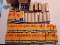
Happiness! Thanks to yesterday's flea market on our national radio hobbyist's day, I got my hands on plenty of original, new Philips TV tubes - PL36, PL82, PL83, PY82, PY80 and EZ41. The ones on the top are 4P1L, EAA91 Telefunken and some 6N2P/3P, but they aren't TV tubes. Don't ask me for the cost, it is ridiculously low.
great find.....a couple of years ago, we also picked a shop of 1800 pcs of tubes, shops like those are still being discovered in Manila...
those who stopped selling tubes in the 80's are now taking out their stocks and again selling.....srill we hear some stories of shops dumping them on trash bins....
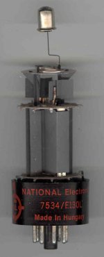
I got a couple of National (Tungsram) E130L tubes off Ebay, and one of them was defective. (it got replaced!) So the opportunity for tube dissection of this interesting tube has arisen. Where's my hammer!
Pics:
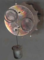
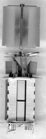
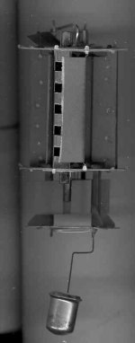
1) E130L busted. Notice the extended cooling fins up top for grid1 and also the plate.
2) E130L bottom view, notice the grid1 bonding plates (one fell off), these were not properly spot welded to the grid1 support rods. No connection between grid1 and the base pins. Notice how big the grid support rods are. This is making for some rather long grid2 wires.
3) E130L side view of plate after grinding off a corner from it
4) E130L half of plate removed to see grids and cathode, the inside of the plate is above (notice the burn marks on the plate, this was used some before failing apparently, or maybe the loose grid1 could not restrain the beam current and burned the plate on first use)
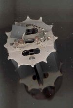
5) E130L top mica with getters
6) E130L close up of grids 1 and 2 at high resolution, surrounded by the shiny beam forming plates. note they both are wire aligned frame grids. Also a cross beam strap (black) between the grid2 support rods. There is also a hidden copper cross beam strap below that for the grid1 support rods.
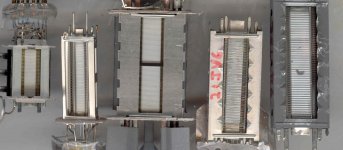
7) grid comparison of some tubes L to R:
12HL7, 6HB6, E130L, 21JV6, 35LR6
The 12HL7 and 6HB6 have a coarser grid2, which is what you see, the grid 1 on these is like 5 or 6 times as finely spaced as grid2 (you can just make out the 6HB6 grid1 wires at max magnification) (the 12HL7 wires are too small to see, just seeing the grid2 shadows at max magnification) 12HL7 is a frame grid. 6HB6 is not, but has nearly the same wire spacing as the 12HL7. 21JV6 and 35LR6 are typical TV Horizontal Sweep tubes.
I'm wondering if the other tube was a failed pull now too. Both were in National boxes. The other tube does perform satisfactorily on the curve tracer. Will have to run it for a while I guess to see if something goes wrong.
..
Pics:
1) E130L busted. Notice the extended cooling fins up top for grid1 and also the plate.
2) E130L bottom view, notice the grid1 bonding plates (one fell off), these were not properly spot welded to the grid1 support rods. No connection between grid1 and the base pins. Notice how big the grid support rods are. This is making for some rather long grid2 wires.
3) E130L side view of plate after grinding off a corner from it
4) E130L half of plate removed to see grids and cathode, the inside of the plate is above (notice the burn marks on the plate, this was used some before failing apparently, or maybe the loose grid1 could not restrain the beam current and burned the plate on first use)
5) E130L top mica with getters
6) E130L close up of grids 1 and 2 at high resolution, surrounded by the shiny beam forming plates. note they both are wire aligned frame grids. Also a cross beam strap (black) between the grid2 support rods. There is also a hidden copper cross beam strap below that for the grid1 support rods.
7) grid comparison of some tubes L to R:
12HL7, 6HB6, E130L, 21JV6, 35LR6
The 12HL7 and 6HB6 have a coarser grid2, which is what you see, the grid 1 on these is like 5 or 6 times as finely spaced as grid2 (you can just make out the 6HB6 grid1 wires at max magnification) (the 12HL7 wires are too small to see, just seeing the grid2 shadows at max magnification) 12HL7 is a frame grid. 6HB6 is not, but has nearly the same wire spacing as the 12HL7. 21JV6 and 35LR6 are typical TV Horizontal Sweep tubes.
I'm wondering if the other tube was a failed pull now too. Both were in National boxes. The other tube does perform satisfactorily on the curve tracer. Will have to run it for a while I guess to see if something goes wrong.
..
Attachments
-
 Grid_compare_HL7_HB6_E130L_JV6_LR6.jpg234.1 KB · Views: 171
 -
 E130L_opened_up6.jpg53.4 KB · Views: 157
 -
 E130L_opened_up5.jpg11.2 KB · Views: 136
 -
 E130L_opened_up4.jpg13.2 KB · Views: 402
 -
 E130L_opened_up3.jpg9.4 KB · Views: 403
 -
 E130L_opened_up2.jpg11.5 KB · Views: 406
 -
 E130L_opened_up1.jpg23.1 KB · Views: 444
Last edited:
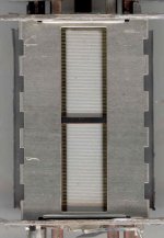
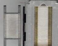
Here is a better pic of the frame grids in the 12HL7 (right side) and a 6JC6 (left side). Scanned at 1200 DPI. That 6JC6 grid is incredible. Still not resolving the individual wires in the 6JC6. Can look right thru it like a crystal.
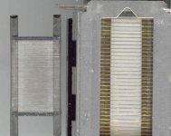
OK, 2400 DPI now. 2nd pic. Can just resolve the 6JC6 wires now (use the magnify function). Looks like they are almost twice as dense as the 12HL7 wires. It must have taken some serious time and ultra precision winders to wind these frame grids.
OK, 2400 DPI now. 2nd pic. Can just resolve the 6JC6 wires now (use the magnify function). Looks like they are almost twice as dense as the 12HL7 wires. It must have taken some serious time and ultra precision winders to wind these frame grids.
Attachments
Last edited:
- Home
- Amplifiers
- Tubes / Valves
- Those Magnificent Television Tubes