wow, any similar diagram for EL34?
Yes, that's exactly the bunch of curves I've given you a hint to in post #173.
Best regards!
Anybody with some 6AV5GA had a chance to lash something up to play with yet? I have the perverse desire to build up a tube car amplifier, and crazy drive sounds like a great way to do it. I'm curious how crazy drive would work with a B+ of around 300 volts and the 12AV5GA, I've even got a pair of generic 6k push pull transformers to use...
partially inspired by milbert amps, which are based on berning amps that use the 6JN6-
http://www.diyaudio.com/forums/car-audio/77471-i-clonning-milbert-bam230-235-car-tube-amplifier-supply-2.html
With a crazy drive output stage, and IRF820 mosfet source followers instead of the 6SN7 cathode followers I think it could be a pretty good way to go. Use a modified 240 volt car inverter with a negative bias transformer added perhaps?
partially inspired by milbert amps, which are based on berning amps that use the 6JN6-
http://www.diyaudio.com/forums/car-audio/77471-i-clonning-milbert-bam230-235-car-tube-amplifier-supply-2.html
An externally hosted image should be here but it was not working when we last tested it.
With a crazy drive output stage, and IRF820 mosfet source followers instead of the 6SN7 cathode followers I think it could be a pretty good way to go. Use a modified 240 volt car inverter with a negative bias transformer added perhaps?
A modified SMPS converter will work wonders! And with H. deflection tubes, one don't need outrageous high B+ so can use ready made internal converter trafos.
A little negative bias SMPS is easy to build from scratch due to low power drain.
LATE EDIT: I posted some commentary about modified converter in same "cloning PSU from Milbert" thread you're mentioned (in quote here), today.
A little negative bias SMPS is easy to build from scratch due to low power drain.
LATE EDIT: I posted some commentary about modified converter in same "cloning PSU from Milbert" thread you're mentioned (in quote here), today.
A little late perhaps, but I will need some PL36 for repair an old Telefunken tube TV, so I can purchase some and make some Twin Driver graphs.Well DIYBras, you have produced some marvellous measurements on this thread; would you be able to generate crazy-drive curves for PL36? I'm sure many on this side of the Atlantic would be thrilled if you could.
Crazy drive sim questions
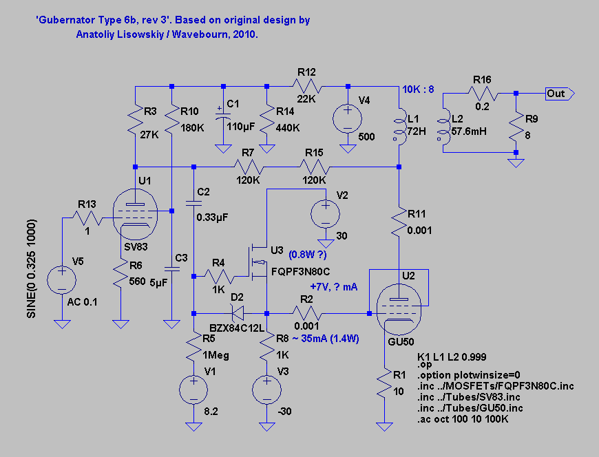
I've been playing with this sim with a view to building something similar.
First thing I noted was that 0.0635Vp was required for 1W output at which point THD was 0.27%.
I wondered why this was relatively poor and tried varying the load resistance to simulate different primary impedance.
The results were most interesting. As load resistance is increased beyond 8Ω THD decreases reaching 0.11% at 9.5Ω. It continues to decrease albeit more slowly, reaching 0.03% at 14Ω. It looks like a 13K transformer would be appropriate.
This seems to be consistent with smoking_amp's statement at the beginning of the thread "too low a Zpri, with low B+, will lead to a load line with significant variation in gm, so higher distortion".
The as built amplifier schematic is also attached.
I've been playing with this sim with a view to building something similar.
First thing I noted was that 0.0635Vp was required for 1W output at which point THD was 0.27%.
I wondered why this was relatively poor and tried varying the load resistance to simulate different primary impedance.
The results were most interesting. As load resistance is increased beyond 8Ω THD decreases reaching 0.11% at 9.5Ω. It continues to decrease albeit more slowly, reaching 0.03% at 14Ω. It looks like a 13K transformer would be appropriate.
This seems to be consistent with smoking_amp's statement at the beginning of the thread "too low a Zpri, with low B+, will lead to a load line with significant variation in gm, so higher distortion".
Last edited:
Why is simulated crazy drive performance poor?
I wasn't sure whether to start a new thread for this or not. The "Ruminations.." thread seems to be dead.
I understand that tube models have trouble getting grid and screen current right and that may well be my problem.
6DQ5 curves were shown here for Rg21 = 1780Ω and Rg1k = 10K.
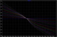
Below are my LTSpice schematic, the curves from the original post (50 mA/div Vert., 50V/div Horiz., and 5.4V steps on g2 down from 68V) and the curves produced by the simulation:


The LTSpice model can’t be too bad because, apart from the slope of the lower screen/grid voltage curves, the results are very similar to smoking-amp’s curves. I've done the same for the 6GB5 with similar results.
Here’s my test simulation for the 6DQ5 output stage and a plot of output THD vs power. 1% and below between 5W and about 70W isn’t too bad but above and particularly below that, performance isn’t great.


Mention has been made of a small negative cathode offset to improve turn off. However, I've tried that, and all sorts of other permutations of screen and grid offset. Nothing really improves the THD performance much.
One of the problems of course is that any change you make to screen, grid or cathode offsets impacts the operating point. Adding a screen offset of +5V or so increases Iq to 40mA and eliminates most of the low power spike in THD (crossover distortion?) but worsens performance everywhere else.
Again, I've performed a similar exercise with the 6GB5 with similar results.
I was expecting better linearity than this. So is the poor simulated open loop performance real or a symptom of poor tube model performance in this mode of operation?
I wasn't sure whether to start a new thread for this or not. The "Ruminations.." thread seems to be dead.
I understand that tube models have trouble getting grid and screen current right and that may well be my problem.
6DQ5 curves were shown here for Rg21 = 1780Ω and Rg1k = 10K.
Below are my LTSpice schematic, the curves from the original post (50 mA/div Vert., 50V/div Horiz., and 5.4V steps on g2 down from 68V) and the curves produced by the simulation:
The LTSpice model can’t be too bad because, apart from the slope of the lower screen/grid voltage curves, the results are very similar to smoking-amp’s curves. I've done the same for the 6GB5 with similar results.
Here’s my test simulation for the 6DQ5 output stage and a plot of output THD vs power. 1% and below between 5W and about 70W isn’t too bad but above and particularly below that, performance isn’t great.
Mention has been made of a small negative cathode offset to improve turn off. However, I've tried that, and all sorts of other permutations of screen and grid offset. Nothing really improves the THD performance much.
One of the problems of course is that any change you make to screen, grid or cathode offsets impacts the operating point. Adding a screen offset of +5V or so increases Iq to 40mA and eliminates most of the low power spike in THD (crossover distortion?) but worsens performance everywhere else.
Again, I've performed a similar exercise with the 6GB5 with similar results.
I was expecting better linearity than this. So is the poor simulated open loop performance real or a symptom of poor tube model performance in this mode of operation?
Last edited:
I've had a go simulating crazy drive in LTSpice before and got similar results. The issue seems to be related to gm doubling. If you look at the output signal you can see a change in slope when tube transitions from class A to class B. In real life there may be an optimum low bias current where you can get a smooth transition, but modelling doesn't show this.
Crazy drive operating point
Could you elaborate on the highlighted bit please? For example, what does "initial" mean here? Is the implication that there should be a negative offset on the screen or grid wrt the cathode?? Or maybe, some sort of level shift between screen and grid like tubelab's dual drive?
For the 6DQ5, recommended Rg21 and Rg1k appear to be 1.78K and 10K respectively. gm is 10.5mA/V and Rp is 5.5K. For a B+ of 500V Vneg is ~17V. Where and how does this need to be applied?
Thanks!
The "Twin/Crazy drive" thing ...
Only after the configuration was put onto a curve tracer did it become apparent that the R connection could be optimized for increased linearity besides increased gm. Further testing with the curve tracer made it apparent that a bottom 2nd resistor, grid1 to cathode, was helpful, and also that the initial drive signal needs to go negative to cathode somewhat, to overcome plate voltage effect for full turn-off. Vneg = 2 x (B+) x 1/(gm1 x Rp)
Could you elaborate on the highlighted bit please? For example, what does "initial" mean here? Is the implication that there should be a negative offset on the screen or grid wrt the cathode?? Or maybe, some sort of level shift between screen and grid like tubelab's dual drive?
For the 6DQ5, recommended Rg21 and Rg1k appear to be 1.78K and 10K respectively. gm is 10.5mA/V and Rp is 5.5K. For a B+ of 500V Vneg is ~17V. Where and how does this need to be applied?
Thanks!
The negative screen voltage requirement is for when the plate voltage swings to near 2 x B+ in a P-P stage. This is to counter the turn on effect of HV on the plate, so that the tube will stay turned off when the plate is at 2 x B+.
So the driver should allow screen voltage to drop somewhat below 0V when turning the tube off in the opposite 180 deg cycle. The formula:
Vneg = 2 x (B+) x 1/(gm1 x Rp) Gives a good estimate of how much negative Vscrn (and Vgrid1) is required to keep the tube turned off when the plate is at 2 x B+.
You just need a pull down resistor on the Mosfet driver source terminal that goes down to this Vneg level. (use bias V supply maybe)
The Crazy drive resistors themselves (Rg1k) still just go down to the cathode.
----------------------------
For class AB crossover, Crazy drive reverts mostly to grid1 drive near cutoff. The way gm is held constant throughout most of the plate curve range is by allowing grid1 to contribute to the total gm when screen gm is low (low plate current). As screen gm picks up at higher plate current, the grid1 current thru the Rg2g1 resistor limits the contribution of grid1 to the gm.
At low plate current, the gm is near totally dependent on grid1. And at very low plate current the grid 1 gm drops off per usual for a grid 1 drive. (insignificant grid1 current, so looks like V drive now) So crossover should be similar to a grid 1 driven tube, but is done at a rather lower current than normal, since the combined gm (of both tubes) never climbs above the nominal grid2 gm.
So grid1 provides some boost to grid2 at low currents to compensate for low gm2. But drops out as gm2 takes over at high currents. At very low currents only gm1 is active. The crossover region only needs to sum to a nominal gm sum that is developed by grid2 in the upper range. So crossover tube current (idle current) will be much lower for Crazy drive than for normal grid1 drive.
So a Spice simulation of Crazy drive crossover need only use standard grid1 V driven tubes, but operated in a low current region where the gm1 sum is just the low nominal gm2 level.
Since gm varies roughly as the SQRT of current, and the gm of grid1 is typically 4X that of grid2 (typical sweep tube internal Mu), then the crossover (idle) current would be something like 1/16 of a typical grid 1 drive stage to maintain a constant gm sum in crossover (of a level developed by grid2 in the higher current range).
This would make Crazy drive class AB quite efficient.
Last edited:
On that 1/16 of normal idle current estimate for crossover (for class AB Crazy drive), some upward adjustment is likely needed. Here ^ means to the power
For a general n power law: Ip = k Vg^n
Gm = (n/k^n) Ip^((n-1)/n)
The Ip^((n-1)/n) being the important factor for gm variation versus current.
For an n=2, or a square law device: gm varies as Ip^0.5 or as SQRT(Ip)
Which is what I used for the 1/16 idle current calc. { 1/mu = 1/4 = SQRT(1/16) }
For Sweep tubes, gm varies more like as Ip^0.6666 for lower practical currents. Which would be n = 3
Which would give a reduction of idle current as 1/8 instead of the 1/16 for the n = 2 case.
However, the power law n for all tubes increases towards lower currents. (likely not accounted for in a Spice model) And for cutoff this would take n to higher levels yet than 3. This continuous n variation would have to be averaged out to do any calculation. For n reaching an exponential, or n infinite, that { (n/(n-1) } would then give 1/4 idle current, so actual idle current reduction will be between 1/8 and 1/4 I think. So the realistic reduction in cutoff current for getting g1 gm reduced to 1/4 of usual value (1/Mu internal) would be more like 1/6 of the usual class AB idle current, rather than 1/16. (obviously a guesstimate! )
One will have to experimentally determine the reduced idle current for smoothest crossover (constant gm1 sum matching gm2 at higher currents). (versus the normal grid 1 class AB operation idle current)
Last edited:
What did you use for {lev_screen}?One of the problems of course is that any change you make to screen, grid or cathode offsets impacts the operating point. Adding a screen offset of +5V or so increases Iq to 40mA and eliminates most of the low power spike in THD (crossover distortion?) but worsens performance everywhere else.
On that 1/16 of normal idle current estimate for crossover (for class AB Crazy drive), some upward adjustment is likely needed. Here ^ means to the power
For a general n power law: Ip = k Vg^n
Gm = (n/k^n) Ip^((n-1)/n)
The Ip^((n-1)/n) being the important factor for gm variation versus current.
For an n=2, or a square law device: gm varies as Ip^0.5 or as SQRT(Ip)
Which is what I used for the 1/16 idle current calc. { 1/mu = 1/4 = SQRT(1/16) }
For Sweep tubes, gm varies more like as Ip^0.6666 for lower practical currents. Which would be n = 3
Which would give a reduction of idle current as 1/8 instead of the 1/16 for the n = 2 case.
However, the power law n for all tubes increases towards lower currents. (likely not accounted for in a Spice model) And for cutoff this would take n to higher levels yet than 3. This continuous n variation would have to be averaged out to do any calculation. For n reaching an exponential, or n infinite, that { (n/(n-1) } would then give 1/4 idle current, so actual idle current reduction will be between 1/8 and 1/4 I think. So the realistic reduction in cutoff current for getting g1 gm reduced to 1/4 of usual value (1/Mu internal) would be more like 1/6 of the usual class AB idle current, rather than 1/16. (obviously a guesstimate! )
One will have to experimentally determine the reduced idle current for smoothest crossover (constant gm1 sum matching gm2 at higher currents). (versus the normal grid 1 class AB operation idle current)
Would it not be possible to put an 'n' calculator into the Spice loop so that n varies with plate current as dictated by the theory? Improve the model IOW, yes?
cheers,
Douglas
Crazy Drive on the air?
Hello!
I'm planning to build a Twin/Crazy drive amp. Having followed all the Crazy Drive threads on this board for several weeks now, I have to say I'm impressed with the idea and the work that has been put into it. Well done!
My build will be a retro-fit for an old amplitude modulated amateur radio transmitter (Heathkit DX-100) so will be used for voice only — music is verboten on ham radio. It needs to provide 100W into a 11k ohm load. It will use 26DQ5's PP w/ 800V(!) on the plates. Those are the givens... 100W, 800V, 11k p-p load. I'm trying to find a cost-effective modification for this popular old radio that will make it sound very good, and can be easily duplicated.
There are others that modify these old transmitters but there are none that I know of who have successfully implemented a dual drive scheme. Now, the recipe seems to have been found!
The amp line-up I have in mind is a 12AX7, 6CG7 LTP splitter w/CCS tail, MOSFET source followers, 26DQ5's in crazy drive. I was planning to use 'DQ5's before I found all this crazy drive stuff. And wow, will it make it easier to implement! I mean, what's not to like about crazy drive? I can find no other source for this technology, and I'm not an EE, so I ask here.")
It has been mentioned that the p-p output impedance using crazy drive is high. Would the 11k p-p load that my transmitter presents be close to good? I hope to use some NFB anyway, but would it be needed to adjust to that load?
My modulating impedance is your speaker impedance, so to speak. My modulation transformer, your OT. So, everything ahead of the output iron is the happy place we have in common. So, this isn't about RF, it's about audio — really good audio. Really good DIYaudio!
Thanks,
Don
Hello!
I'm planning to build a Twin/Crazy drive amp. Having followed all the Crazy Drive threads on this board for several weeks now, I have to say I'm impressed with the idea and the work that has been put into it. Well done!
My build will be a retro-fit for an old amplitude modulated amateur radio transmitter (Heathkit DX-100) so will be used for voice only — music is verboten on ham radio. It needs to provide 100W into a 11k ohm load. It will use 26DQ5's PP w/ 800V(!) on the plates. Those are the givens... 100W, 800V, 11k p-p load. I'm trying to find a cost-effective modification for this popular old radio that will make it sound very good, and can be easily duplicated.
There are others that modify these old transmitters but there are none that I know of who have successfully implemented a dual drive scheme. Now, the recipe seems to have been found!
The amp line-up I have in mind is a 12AX7, 6CG7 LTP splitter w/CCS tail, MOSFET source followers, 26DQ5's in crazy drive. I was planning to use 'DQ5's before I found all this crazy drive stuff. And wow, will it make it easier to implement! I mean, what's not to like about crazy drive? I can find no other source for this technology, and I'm not an EE, so I ask here.
It has been mentioned that the p-p output impedance using crazy drive is high. Would the 11k p-p load that my transmitter presents be close to good? I hope to use some NFB anyway, but would it be needed to adjust to that load?
My modulating impedance is your speaker impedance, so to speak. My modulation transformer, your OT. So, everything ahead of the output iron is the happy place we have in common. So, this isn't about RF, it's about audio — really good audio. Really good DIYaudio!
Thanks,
Don
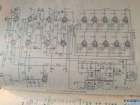
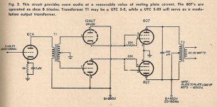
Is this another screen/crazy drive (existed longer ago), 250W amp for cinema use. It works without the OT, provided you have correct speaker system, really is high voltage OTL (480V bipolar).
Attachments
Last edited by a moderator:
Hi there, if I understand correctly from the Chinese bbs, the main signal drive input is still grid no.1 (despite 20k resistor).
For pentode to be a triode connected, the screen is normally connect to the plate and has nearly the same potential (and implied 100% NFB), but here the screen has neither, which is zero (no positive voltage, no NFB) and acts like current controller but when it's driven the current start to follow and perhaps contribute to signal drive to output because inter-stage transformer is capable of driving screen grid positive much like the MOSFET driver in screen/crazy drive. In the 50's there is not solid state equivalence yet, but I think they did virtualise these possibility then.
For pentode to be a triode connected, the screen is normally connect to the plate and has nearly the same potential (and implied 100% NFB), but here the screen has neither, which is zero (no positive voltage, no NFB) and acts like current controller but when it's driven the current start to follow and perhaps contribute to signal drive to output because inter-stage transformer is capable of driving screen grid positive much like the MOSFET driver in screen/crazy drive. In the 50's there is not solid state equivalence yet, but I think they did virtualise these possibility then.

- Status
- This old topic is closed. If you want to reopen this topic, contact a moderator using the "Report Post" button.
- Home
- Amplifiers
- Tubes / Valves
- More Ruminations on Screen Drive/Crazy Drive