Good to hear that someone liked the 12HL7 for sound. The triode curves look so perfect that one worries whether it is -too- clean.
What B+ got used for the 12HL7? The 330V spec for grid 2 at least gives a little room (versus Sweeps at 220V).
the amp that i used the tube in was anemic and somewhat slow according to the owner, replacing the 26 tube, the difference was much noticeable....
18 Watt 21HB5's were $1 a few years back, so 500 Watts worth would be $28
I'm looking to build a 500 watt per channel stereo tube amp. You don't need 500 watts of plate dissipation for that.
If you design the amp to be capable of putting out 500 watts per channel of continuous sine wave power (1 KW total), and you get 60% plate efficiency then you would need about 333 watts of dissipation capability per channel. That's 1667 watts of DC into the tubes, 60% of which gets turned into audio (1KW) and the rest (667 watts) gets burned up as heat. These would be valid assumptions for say a shaker table amp.
I don't make a habit of listening to 1KW sine wave tones for hours, and even bass heavy super compressed EDM has a peak to average ratio of 10 db (often called crest factor, even though the definitions are somewhat different). This means that a 1 KW dance music amp cranked to the edge of clipping will be producing about 100 watts of AVERAGE power. This number is far lower in a typical HiFi amp playing music that was reasonably recorded. This means that out 1 KW amp may survive for years with 100 watts of dissipation capability. Bob Carver made his career by exploiting this fact. An ordinary class AB1 sweep tube amp can make 525 watts of power with 4 X 35LR6's, I did this with one of Pete's big red boards. The tubes began to show red after about 1 minute at full power. This is acceptable, and will be plan "B" if the high efficiency experiments don't work out.
I got one of the original Carver M400 "Magnetic Field Amplifier" when it came out in the early 80's. It was a metal cube about 8 inches on a side with NO heatsinks. It was rated for 200 WPC into 8 ohms, and made about 350 WPC into 4 ohms. It had warnings in the manual that it was for HiFi use only and was not to be used for musical instrument applications.......Did I plug my guitar into it.....you know it. It would crank out some extremely loud metal shredding for a few minutes, then shut down until I gave it a minute or so to catch it's breath. It did not get hot though. I could play the guitar through it for hours at ear splitting levels, just as long as I kept the last LED from lighting up too often (clipping). The amp used three different power supply rails and engaged only what was needed at the time.
I later found out that blowing up the power amp wasn't the issue. The tiny power transformer would overheat and fry. Out of the 10 Carver "cubes" purchased by our audio club, mine was the only survivor after about 15 years of abuse.....the others all died from Florida lightning induced power supply death. The amp had no power switch, and the manual stated that it had to be plugged directly into the wall outlet and NOT into your preamp's switched outlet, which is exactly where I plugged mine, a Phase Linear (Carver) 4000 sonic hologram preamp.
Why the long winded dissertation about Carver? Because we can exploit the exact same principles. I plan to use a class H type 3 (or more) rail power supply. This, however only works with a cathode follower output stage. I have made this work at low power levels, but it remains to be seen if a 500 watt P-P cathode follower can actually be built....and more important can it's driver be built?
If so, I can run the output tubes in class A and make extremely large amounts of power.......time will tell.
Secret Hint: Most of the single-plate 42KN6's or 6KN6's are actually 36KD6/6KD6; the -KD's have extra connections for the grids ; easy to check. On my SOFIA I note that the double plates run the higher heater current; the singles again match the 6KN6 current. On the Bay; delivered today; a 6AC10 and a 42KN6 NOS Westinghouse; shipping and everything $6 for BOTH. Checked the pins on it; it's a 36KD6. It completes my NOS Westinghouse Quad; I splurged $25 on the other 3. The only exception to that rule are the Japanese single plates; they lack the connections and run higher heater current.
I have several of the twin plate 6KN6's. I tested those because of the high peak current capability, but they red plate easily in the area between the plates. Not a candidate for this amp. I have one 36KD6 / 40KD6 tube. It has the same size plates as the 36LW6, but since I only have one, it may not get tested.
That is the simplest possible method, but likely 2 or 3 parallel tubes. Peak cathode current requirements will determine how many.
Below is the ultimate setup. Reality at 500 WPC is likely some combination of the two, possibly with an "augmented cathode follower loop" added for near infinite PSRR. (have tested ACF's as output stages, again at 20 WPC in SE). P-P cathode followers add complications since the driver must now swing negative, requiring bipolar supplies at 700 volts! Circlotrons avoid this, but make modulated or rail switched supplies very complicated.
About 10 years ago I built a 20 watt SE amp using a 6AS7. It used a modulated SMPS for the plate supply of a cathode follower output stage. I had been working on modulated power supplies for linear RF power amps at work, so I had a head start on the technology.
The amp used a dsPIC chip to create an SMPS whose output varied in step with the applied audio over a range of 100 to 350 volts. This was applied to the plate of a 6AS7 cathode follower output stage. Cathode followers inherently have a high PSRR so a 10 bit (1024 steps) representation of the audio modulated power supply is far better than Carver's 3 stage approach.
This worked great at 20 WPC, and won a prize in a Circuit Cellar / Microchip design contest that resulted in magazine publication in 2007. The reality of a 250 volt P-P audio signal modulated power supply was hard to tame in a 20 WPC amp, but I had the processor chip, the D/DAs for tube bias, and all of the digital amp control features on the same PC board with a pair of SMPS's. The A/D's for sensing and monitoring were inside the PIC chip. I'm not sure it's even possible with nearly 700 volts at over an amp of current.
It's safe to assume that something is going to go KABOOM! I blew up piles of silicon, SiC and GaN during the development of the 700 MHz radio transmitter. Ditto the 6AS7 amp. The next experiments will be using some small expendable sweep tubes, cheap mosfets and some expendable OPT's.
So Mosfets are doing the B+ rail switching for a bank of parallel tubes? A bunch of V comparators to control all this I guess.
That is the simplest possible method, but likely 2 or 3 parallel tubes. Peak cathode current requirements will determine how many.
Below is the ultimate setup. Reality at 500 WPC is likely some combination of the two, possibly with an "augmented cathode follower loop" added for near infinite PSRR. (have tested ACF's as output stages, again at 20 WPC in SE). P-P cathode followers add complications since the driver must now swing negative, requiring bipolar supplies at 700 volts! Circlotrons avoid this, but make modulated or rail switched supplies very complicated.
About 10 years ago I built a 20 watt SE amp using a 6AS7. It used a modulated SMPS for the plate supply of a cathode follower output stage. I had been working on modulated power supplies for linear RF power amps at work, so I had a head start on the technology.
The amp used a dsPIC chip to create an SMPS whose output varied in step with the applied audio over a range of 100 to 350 volts. This was applied to the plate of a 6AS7 cathode follower output stage. Cathode followers inherently have a high PSRR so a 10 bit (1024 steps) representation of the audio modulated power supply is far better than Carver's 3 stage approach.
This worked great at 20 WPC, and won a prize in a Circuit Cellar / Microchip design contest that resulted in magazine publication in 2007. The reality of a 250 volt P-P audio signal modulated power supply was hard to tame in a 20 WPC amp, but I had the processor chip, the D/DAs for tube bias, and all of the digital amp control features on the same PC board with a pair of SMPS's. The A/D's for sensing and monitoring were inside the PIC chip. I'm not sure it's even possible with nearly 700 volts at over an amp of current.
It's safe to assume that something is going to go KABOOM! I blew up piles of silicon, SiC and GaN during the development of the 700 MHz radio transmitter. Ditto the 6AS7 amp. The next experiments will be using some small expendable sweep tubes, cheap mosfets and some expendable OPT's.
is it required to connect grid stoppers on all of them?
I have always just connected one resistor to one pin and left the others NC.
.lot of 14 single plate 36kd6 labelled 42kn6 right now on auction buy it now $52
That lot is a mix of twin plate 42KN6's and single plate tubes of at least 3 different constructions (one is Japanese). Mixing them in the same power amp invites meltdown, especially at the 150+ watts per pair level.
The sweep tubes don't mind a little color on the plates
I have seen TV sets that ran the horizontal output tube with a touch of red. We changed that tube at least once a year. Running a sweep (or any consumer type tube) in the red zone will cause the plate to outgas impurities quicker than normal. This contaminates the vacuum and leads to increased grid current from ion recombination. Unless the grid driving impedance is near zero (mosfet follower drive) the tube will eventually go into uncontrolled runaway.
While looking around on my hard drive for something else, I found the example that makes me distrust the entire lot of 35LR6's that I have. There are some good tubes in there but I would need to do an extreme test on each tube.
This one met the hammer. A good tube has a twist on the tabs at the top of the plate where it comes through the top mica. This keeps the mica from popping off. This tube had no such twist, and neither do most of the other tubes. I got 45 35LR6 tubes in a cardboard box at a hamfest and they were cheap. Perhaps these had been stress tested by UPS somewhere in their history.
You see some unusual characters at a hamfest, but Major Tom?
Some years aog I've got a bunch of NOS Sylvania EL519/6KG6A's. Surely I'll have to go and get a closer look at them...
Seems that I've had some more luck
") :
:The guy who sold these EL519's to me, a former employee at the TELEFUNKEN Ulm tube plant also handed me an individual gm curve per valve.
Best regards!
Attachments
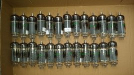
Coincidentally... This is actual number of PL509's I have in good conditions (funcional), but from several makers.Seems that I've had some more luck
The guy who sold these EL519's to me, a former employee at the TELEFUNKEN Ulm tube plant also handed me an individual gm curve per valve.
Best regards!
Red plate and current overload
The OTL amplifiers comes to mind about overload issue. Basically, the current emission overload destroy a tube in OTL amps. If red plate occurs in some occasions, without using all cathode emission capacity, no problem I think.
So I bet that TubeLab 500W amp will survive far more time than a OTL amp.
Coincidentally... This is actual number of PL509's I have in good conditions (funcional), but from several makers.
Still have to count all my used PL505/509/519, also from very different makers
.Best regards!
question: on power tubes that have several grid connections, is it required to connect grid stoppers on all of them? or just one?
You usually find multiple grid connects in tubes intended for grounded grid, VHF amplification. (Multiple cathode connections are seen in types like the 6AK5 intended for common cathode, VHF amplification to keep the ground returns of the plate and grid circuits separate.) At audio frequencies, it's not necessary to make more than one connection. It all depends on the type and how much it likes to make RF, the lay-out, construction practice whether you can float the unused grid pins and still remain stable.
Have a look at the 6KG6A/EL519 pinout diagram. Every grid, even the beam former 3rd grid, is brought out by two pins with large distances between both of them. I can imagine two reasons for doing it this way: Improved cooling, especially for the screen grid, and improved mechanical stability, which may ease manufacturing in the step when the envelope is pushed over the structure, prior to being melted to the glass bottom.
For normal or audio operation of a sweep tube *imho* it is not necessary to connect both pins.
Best regards!
For normal or audio operation of a sweep tube *imho* it is not necessary to connect both pins.
Best regards!
A problem with the high gm tubes is their variability. Sweep tubes test run 250 plate 120 screen and -22 grid and see anything from 50 to 250 mA; and the gm varies as well. That is why I buy a lot of them and match. The different manufacturers don't matter as long as you match the sets. I usually run 1 bias adjustment per channel for single tubes and 2 if they are paralleled. All tubes on a bias adjustment need to be matched.
The 6HJ5 datasheet mentions that the extra pins for the grids are useful for cooling purposes if heavy wire leads are connected to them:
http://tubedata.milbert.com/sheets/084/6/6HJ5.pdf
I suppose that would entail a grid stopper on each pin if the wires go anywhere enough to pick up a Pos. Fdbk signal.
http://tubedata.milbert.com/sheets/084/6/6HJ5.pdf
I suppose that would entail a grid stopper on each pin if the wires go anywhere enough to pick up a Pos. Fdbk signal.
That lot of 14 42kn6 are on their way to me. $38. ;-) I use an outboard filament xfmr to run curves/match on my SOFIA. The MELOS chassis that I gutted and rebuilt is running Doubles (6KN6) on one channel and Singles (6KD6) on the other. The MC275 xfmr set is running 36KD6 labelled 42KN6 (Singles). Front end on both amps is compactron. The sound is most definitely not 6550's.
- Home
- Amplifiers
- Tubes / Valves
- Those Magnificent Television Tubes