"seems that he did have many interesting ideas though..."
Indeed, miss the old guy. His ideas definitely got you thinking, even if you didn't agree with them all the time. Totally different perspectives. Plus some oddities, like design rules that forum members supposedly enforced (according to him), which were a bit insulting at times, and then a set of rules that He followed for the golden tube way. Was a bit like a board game where certain moves were legal, and others weren't. Seemed like the bandwidth there stretched from genius to absurdity, a little hard on some members to swallow.
I recall he insisted that a draw-able signal path from input to output was all important, and could not be violated with SS devices, but SS devices not in the serial path were OK. That caused a few arguments about shunt effects and Kirchoff's laws. Well, was easy for anyone to get into arguments with such rigid rules, one of them must have blown up.
Just browsing the thread and found this. My favorite project so far is a Darius (oldeurope) inspired Loftin/White amp. Too bad we couldn't find a way to let his idiosyncracies pass. I've learned to appreciate some "odd" folks.
Sheldon
I'm strongly considering using "crazy mode" on some 6DQ5s in a revamped version of my "Miz Piggy" amp, which has been languishing in a box lately due to shortcomings with its square wave response and overall listenability. It was a nice amp once upon a time, and I'd like to restore it to esteemed status again, as it was one of my first tube amps that I actually completed.
"Considering crazy drive over triode connection for the 11hm7."
The 11HM7 does not have aligned grids for reducing screen grid current. (typical Horiz. output tubes are grid aligned.) So trying to drive the 11HM7 with Crazy drive will put a heavy current load on whatever is driving it. The 11HM7 has an internal Mu around 31, so grid 2 is much less sensitive (less gm) than grid 1 besides. (sacrificing 31X gain)
Or did you mean Crazy drive of the output tube?
11HM7 and 12HL7 are fairly similar. Neither has aligned grids, both are frame grid 1. 12HL7 at least has a more standard heater voltage. And 12HL7 are available for $1 at ESRC. (the $1 list) (11HM7 $3)
The 6HJ5 you mentioned would be the one I would expect to be "Crazy Driven". (Driven Crazy?) Its got aligned grids and 24 Watt plate dissipation with no plate cap. $4. There is also 26DQ5 available for $3 (24 Watt, octal, plate cap, 26V heater). Both are fairly similar tubes as far as characteristics go. And 21LG6A is similar also, $4 28Watt, with a plate cap, 21V heater though. Also 6CB5A for $5. (octal, plate cap, 26Watt)
The 6HJ5 you mentioned would be the one I would expect to be "Crazy Driven". (Driven Crazy?) Its got aligned grids and 24 Watt plate dissipation with no plate cap. $4. There is also 26DQ5 available for $3 (24 Watt, octal, plate cap, 26V heater). Both are fairly similar tubes as far as characteristics go. And 21LG6A is similar also, $4 28Watt, with a plate cap, 21V heater though. Also 6CB5A for $5. (octal, plate cap, 26Watt)
Last edited:
6DQ5 crazy drive amplifier....
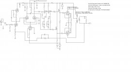
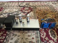
I am going to try and share a ltspice file of my crazy drive amplifier. I have never attempted to share a schematic before so I hope this works. The amplifier is a project in continuing development but I can say it works very well at this time and sounds great to my ears which are far from perfect. I have not worked on it much in the past month as the better weather is upon us here in Oregon. But I will tweek it more as time goes on. I am always open to ideas on how to make it better.
Mickeystan
Attachments
Last edited:
Tried to make it see-able.
One thing I notice is the Mosfet drains could use a series resistor to limit current to the screens. Although the grid2 stopper resistors could do that also, but will lead to distortion effects if too high in value.
One thing I notice is the Mosfet drains could use a series resistor to limit current to the screens. Although the grid2 stopper resistors could do that also, but will lead to distortion effects if too high in value.
Attachments
Last edited:
+1Tried to make it see-able.
One thing I notice is the Mosfet drains could use a series resistor to limit current to the screens. Although the grid2 stopper resistors could do that also, but will lead to distortion effects if too high in value.
My analysis about it, if I cannot made some error: a drain series resistor barely change MOSFET follower behaviour, maintaining low output impedance to feed the screens, even with "high" resistor values. So MOSFET drain resistor will offer protection and low drive impedance.
Someone else mentioned the Drain resistor idea recently, and it is a good idea.
G2 drive setups can overdrive the screen grid occasionally.
One other thing needed then would be a 12V, or so, protection Zener across the Mosfet Source to Gate, for protection of the gate when the Drain resistor limits the current. (The gate would still swing positive when overdriven, but the screen grid would not, due to lack of current, so the Zener clamp protects the Mosfet gate by loading down the previous stage.)
One other thing needed then would be a 12V, or so, protection Zener across the Mosfet Source to Gate
It took me far too long to figure this out. Several mosfets lost their lives.....even ones with built in gate zeners. Those are big enough to stop ESD from blasting a gate, but not big enough to eat all the charge in a coupling cap.
I have same experience with protected vertical MOSFETs, but for some reason, I'm unable to blow the lateral MOSFETs internal zeners in my version of this hybrid: solidstateamps5+tube-input fig. 5 but with 6CL6 in drive position, and proper bias to 6CL6. Note Pat Turner uses external zeners, but I relied solely to internal zeners protection (lazy, crazy or both  )...
)...
And in 2009 I blew some EXTERNAL 1/2W protection zeners with a 6DJ8 SRPP, with far less current bias than the 6CL6 Turner-like version, in open loop (so no feedback to clamp current in the zeners), go figure... but I'm sure the 6DJ8 amp oscillated, and my recent 6CL6 completion never oscillated in RF.
PS.: maybe will be better to include the external zeners to avoid some fire in my loudspeakers...
)...And in 2009 I blew some EXTERNAL
1/2W protection zeners with a 6DJ8 SRPP, with far less current bias than the 6CL6 Turner-like version, in open loop (so no feedback to clamp current in the zeners), go figure... but I'm sure the 6DJ8 amp oscillated, and my recent 6CL6 completion never oscillated in RF.PS.: maybe will be better to include the external zeners to avoid some fire in my loudspeakers...
Last edited:
Hellow Smoking-amp, DIYBras and tubelab, Thanks for the feedback. I will add some drain series resistance to the B+, the idea makes a lot of sense to me. I too have paid the price on no gate protection with back to back zener diodes. So I know the need for protection is spot on. I did not realize that I had not updated my schematic, I actually built the amp using MosFets with internal protection diodes, so I am already protected. One other recognition, for Smoking-amp, the voltage divider ratio of resistors on the 6DQ5 tubes (screen, to control grid and onto ground) is the values he recommended. This was my first go at a screen grid drive amp originally and I decided to try the crazy drive just for fun at the last minute. I have actually run the amp as a screen drive amp with the control grids tied straight to cathodes and it works very well in this fashion too.
I would like to see other peoples approach to screen driven amps or crazy drive amps as the tread goes on. Did anyone else see anything fundamentally wrong or needing improved in the little project? Thanks to all for the feedback. Mickeystan
I would like to see other peoples approach to screen driven amps or crazy drive amps as the tread goes on. Did anyone else see anything fundamentally wrong or needing improved in the little project? Thanks to all for the feedback. Mickeystan
"the voltage divider ratio of resistors on the 6DQ5 tubes (screen, to control grid and onto ground) is the values he recommended."
Those R values were from eyeballing the curve tracer while turning some Pots for the two resistors. Hardly an accurate distortion analysis, and the variation is quite slow on the curve tracer. So take those values with some mild scepticism. Once you have everything working well, you may want to tweak those values some if you have a distortion analyzer and some Pots (the distortion residual sent out to an O'scope) or an FFT (sound-card) or even just by listening. I'm sure the distortion can be optimized further with better measurements to see it. Especially check on the crossover between the P-P sides in class aB (the analyzer residual on the O'scope will see it directly). (some periodic matching up of the two P-P sides R divider values from the Pots may be needed during testing, to optimize)
I would also check the crossover dist. versus the idle current levels (bias) of the output tubes when you get a chance. We really have no idea yet how this crazy drive thing wants to be biased. It seems that g2 only drive may like low idle currents, so crazy drive might be a similar case. Crazy Drive seems to keep the tube gm constant throughout the current range, which if that continues down to small currents would cause gm doubling where the tube conduction overlaps. The gm on the tracer does however seem to finally reduce at very low currents, so there may be a low optimum idle current. Completely unknown at this point.
Last edited:
smoking-amp, thanks for the feedback on the optimizing of the resistor ratios. Yes, I do have a HP distortion analyzer and a good Tek scope so looking at the residual from my distortion analyzer. I will take the advice and look at the residual with some different ratio values and different bias points when I get back to messing with the amplifier. Right now I just turn it on and listen to it when I am out in the garage working on my hotrod, 37 Ford 5 window coupe. Thanks again for the feedback and insites.... Mickeystan
Crazy Drive Tuneup
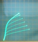
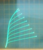
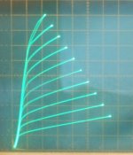
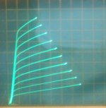
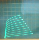
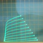
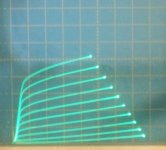
I ran off some 6HJ5 curves with different Rg21 values. (Rg1k was around 10K for all) (6DQ5 is very similar to the 6HJ5)
These were all at 50 mA/div Vert., 50V/div Horiz., and 5.4 V steps on g2 down from 68V. (except g2 only drive and pic 2 were at 6.5V steps)
1) g2 drive only (6.5 Vsteps down from 68V for this one)
2) Rg21 = 19700 Ohms (6.5V steps down from 68V)
5.4V steps for these:
3) Rg21 = 2750 Ohms peak Vg1 = 1.7V peak Ig1 = 5 mA (so like 8 mW peak diss. for g1)
4) Rg21 = 1780 Ohms peak Vg1 = 5.0 V peak Ig1 = 30 mA (so like 0.15 Watt peak diss. for g1, average would be about 1/4 of that) (this is the type curve set I select for)
5) Rg21 = 700 Ohms peak Vg1 = 10V peak Ig1 = 140 mA (1.4 Watt peak diss. for g1, NG)
6) Rg21 = 600 Ohms peak Vg1 = 14V peak Ig1 = 180 mA (2.5 Watt peak diss. for g1, NG!!)
7) Rg21 = 350 Ohms (didn't measure this one, takes too long, might poof it)
The Rg21 = 1780 Ohms is the region (well, this type of curve) I typically selected for the resistor values posted earlier.
Higher Rg21 Ohms reduce the gain (peak current) but seem to still do well at linearizing the curves. More peak Vg2 needed to reach the same plate current. 2750 Ohms and above seems to be where most gain effects from g1 drop out, but linearization effects seem to extend up to the 19700 Ohm level.
G2 only drive lacks the obvious linearization and requires the most Vg2 drive to reach similar plate current.
Lower values of Rg21 start to significantly increase the heating of grid 1 and eventually produce gross distortion at high plate current as seen. (g1 absorbing the plate current at low Vp)
So some current limiting for the Mosfet follower(s) is a very good idea when adjusting Rg21 for distortion or gain.
-
Attachments
-
 rsz_6hj5_cr_350_50_50.jpg56.9 KB · Views: 60
 -
 rsz_6hj5_cr_600_50_50.jpg57.5 KB · Views: 58
 -
 rsz_6hj5_cr_700_50_50.jpg65.2 KB · Views: 766
 -
 rsz_6hj5_cr_1780_50_50.jpg67.3 KB · Views: 793
 -
 rsz_6hj5_cr_2750_50_50.jpg63.1 KB · Views: 794
 -
 rsz_6hj5_cr_19700_50_50.jpg64.8 KB · Views: 801
 -
 rsz_6hj5_cr_g2only_50_50_6,5.jpg57.4 KB · Views: 815
Last edited:
Changing the other resistor (for Crazy Drive) Rg1k seems to mainly effect the curves in the 0 to 50 mA plate current region (effects the gain there).
Some tubes seem to develop a gain bulge in this low current region, and a lower Rg1k (about 2X Rg21 typically) seems to fix that. Making Rg1k TOO low however, will lower the gain for all the curves. (knocks out g1 effects)
Occasionally I found a tube that also needed a small voltage offset from 0V (or cathode V, typically 0 to -1.5V offset needed) for the bottom of Rg1k to fully fix the low current gain bulge. I would guess this is due to some thermo-electric offset in the tube from dissimilar metals bonded.
6CD6 amp. As straightforward as a stick. Pentode output, regulated screen grid supply, cathode self-bias. 33W each dissipates. Sounds fantastic without any sneakiness. Almost 10W on onset of a "round" clipping. Waiting for transformers, Westons promised to ship them June, 22..... waiting....
Attachments
- Home
- Amplifiers
- Tubes / Valves
- Those Magnificent Television Tubes