The 'BG6's ARE 6L6oids and can be run in any 6L6 design. The original 6BG6 appeared at the time the 6L6GA was common so any BG6 from that time period would contain 6L6GA guts. The BG6 was manufactured all the way through the 6L6GC era so there were plenty of BG6s with 6L6GA, 6L6GB, and 6L6GC guts.
Sylvania was famous for stuffing the glass with whatever they had on hand to fulfill military contracts, and this is what led to the "super 6BG6." It's a 6BG6 bottle with 7027A guts inside. The 807 is also cloned from the 6L6 family tree and I have seen 807 with all the common 6L6 family guts inside as well. The screen voltage and plate dissipation capability of a BG6 tube will depend on which guts it contains, but 400 volts in triode seems safe on any 6L6 type I have tried even the old metal tubes, if you keep the total dissipation a safe distance from the red zone. You can also push the voltage a bit higher in class AB push pull since the average dissipation is usually lower than class A.
I have no experience with the EX6 tubes.
I have had 4 different 6LW6 tubes go into red plate runaway operating them in class A SE triode mode. They all ran away while sitting idle which is worse case in class A. Some lived for 6 months or so before running away to their death. After the first tube died, I just popped in another tube and the amp lived on for a few months and the other tube died. These were running just over 400 volts. I reduced the plate voltage some (don't remember how much) and within months a third tube died. Then I swapped the power transformer to bring the B+ down to 350 volts or so. A 4th tube died so I dismantled the amp. These were all fat bottled GE made tubes similar to the Admiral branded tube in your picture.
I have several skinny Sylvania made tubes, but all new experiments have been done with the screen voltage safely below 200 volts and no issues have been seen to 700 volts on the plate. I have seen 250 watts from a pair of these in pentode.
I am currently debugging a pseudo triode mode for big power, but I'm still fighting some little gremlins that keep my amp from making me happy. All testing for the new mode has been constrained to $1 tubes for economic reasons but 75 watts from a pair of $1 tubes isn't too bad.
Unrelated to topic, but only for curiosity, the metal tubes are capable to make red it's outer surface, with "proper overload"? I never tried it. I don't have dud metal tubes for trying it...<snip> .... 6L6 type I have tried even the old metal tubes, if you keep the total dissipation a safe distance from the red zone. You can also push the voltage a bit higher in class AB push pull since the average dissipation is usually lower than class A.
......
.
I know that glass tubes like 6AQ5 or PL509 can melt it's glass surface if anode gets too hot.
Anyone have played with this?
Tubelab George has melted and blown up just about any tube in the name of science, including metal 6L6s if I'm not mistaken.
And i read one time here about somebody trying to blow up a PL504 or similar euro sweep tube.
Didn't blow. Finally the glass melted. Such an anticlimax")
Still I'm not sure if iwanted to be close to the event that lead to the 'dent' in the side of an 813 that i found at an old electronics fair. Big tube... Thick glass... Melting??
And i read one time here about somebody trying to blow up a PL504 or similar euro sweep tube.
Didn't blow. Finally the glass melted. Such an anticlimax
Still I'm not sure if iwanted to be close to the event that lead to the 'dent' in the side of an 813 that i found at an old electronics fair. Big tube... Thick glass... Melting??
the metal tubes are capable to make red it's outer surface.......Anyone have played with this?
I successfully won a bet with the teacher in my high school electronics class my making the outer metal envelope glow a dim pale red color on a metal 6L6.
Ordinary melting methods will not work. You need several power supplies, with some applied to the 6L6's normal elements and adjusted such that the plate will glow bright red. This can be verified with a glass tube before installing the metal tube.
A second power supply capable of several hundred mA and a fairly high voltage is added with the negative lead on the plate (pin 3) and the positive lead on the shield (metal shell, pin 1). I think we had two 400 volt 200 mA supplies wired in parallel. After the plate of the tube is hot enough to emit electrons, and some time passes to make the tube "gassy" (a few minutes) the second power supply is switched on such that the glowing plate is now a cathode, and the metal shell it the plate. Adjust the "heat" in this new cathode (6L6 plate) by controlling the dissipation in the original 6L6 electrodes. The object is to vary the heat in the original plate to maximize the dissipation in the "new" plate (the metal shell). Too much heat, and the current goes up, but the voltage drops, too little heat and the current drops. This is all determined by what the power supply feeding the metal shell can deliver.
It took a couple of tries to get this right. If you take too long the internal glass to metal seal will fail and the tube will go to air. Try to go too fast and the 6L6 guts may fail.
WARNING!!!!!!! We did this in a high school class room in a non airconditioned school (well ventilated) in 1969. It stunk up the place bad with the odor of burning plastic and all the paint peeled off the shell early in the experiment. Doing this today might be considered CRAZY, UNSAFE, or just plain STUPID!!!!! I will not repeat this experiment today. I wouldn't advise anyone else to do it either, mainly due to the stink created by the fried Bakelite base. Who knows what toxicity lives in that stuff.
Sometime later I did the same trick with a 6AS7GA only I got the big power supply connected between the two plates. All sorts of cool colored gaseous discharges went on inside the tube, and eventually the tube got hot enough that the glass began to MELT. As the glass became soft it bulged OUTWARD. I had not only used up all the vacuum, I created a positive pressure. I killed the power just before the glass broke......As expected the tube was rather dead after it cooled off. The only conductivity was the heater.
I WILL repeat this one some day.....in fact I have a gassy 6AS7 sitting on the shelf awaiting its last gasp. I did the original "experiment" in the cal lab at Motorola where I worked. it was just one of our learning experiments, done late at night after all the "normal" people had left the building........we had loads of fun with liquid nitrogen too! Tubes don't like it (especially hot ones) despite what the cryo wackos tell you.
George,
Really cool (ooops... hot ) stuff!
So is possible, but difficult.
400V x 200mA = 80W x2 = 160W, so this not take soooo much power to makes things red. I've speculated serious power (kW) due to air coupling (the case is not being in vacuum), but since the metal can is thin and anode already contributes some heat...
Perhaps I don't need to try this in my home now
Really cool (ooops... hot
) stuff!So is possible, but difficult.
400V x 200mA = 80W x2 = 160W, so this not take soooo much power to makes things red. I've speculated serious power (kW) due to air coupling (the case is not being in vacuum), but since the metal can is thin and anode already contributes some heat...
Perhaps I don't need to try this in my home now
I'm not sure exactly how many of the old Eico power supplies we used, or how they were wired, since it was almost 50 years ago. It was probably two or three of them and we never respected the actual ratings on these things since we abused them like school students did, and they didn't die.
I routinely suck 300 mA or more out of my Knight KG-664 power supply today and it doesn't complain. It will go unstable much above 300 mA though. The old Eico's at school were similar, probably identical to the Knight. So worse case I could have been stuffing 300+ watts into that tube, but I doubt it was that much. I have made similar sized resistors glow red with a couple hundred watts or less.
Air movement makes a big difference. Even a little air flow can improve heat transfer greatly.
I made a load bank for testing a 12 volt to 28 volt boost converter at work. It used a bunch of little 10 watt wirewound resistors all soldered to a PC board. I used a small fan from a PC power supply to blow air across them, and the entire unit would eat the output of the 300 watt power supply without issue as long as the fan was running. I turned the entire project over to a junior engineer who was back within a week with a crispy burnt load bank. He had removed the fan because he didn't like the noise.
Yes, these fans are very good for abusing specs, and even for transformers helps a little. I overloaded one trafo time ago and it smelled a little bad, but survived. Since at that day I don't have a substitute, I put 2 fans, one poiting to one side of windings, and the other close to trafo, sucking out the air. Very good! I can abused it even a little more, without letting the magic smoke to escape.
Well, sometimes I fell a little guilty myself for various OT postings, but since the subject is interesting...
Well, sometimes I fell a little guilty myself for various OT postings, but since the subject is interesting...
I put 2 fans, one poiting to one side of windings, and the other close to trafo, sucking out the air.
If you'd let your fans blow at the source of heat, they would be much more efficient!
Best regards!
Hmmm. Sorry... I write last post in a hurry, so I forget to mention that the first fan was blowing to the trafo. To be fair, if I pointed both to trafo, certainly will be better for it, but I have feared the trapped air around it, due to enclosure (unjustified this time since in fact the "enclosure" are a box without top cover).If you'd let your fans blow at the source of heat, they would be much more efficient!
Best regards!
By the way, for some closed enclosures or tunnelled heatsinks a helper fan pulling the already hot air helps a lot. In my PC I always locate in/out helper cabinet fans in appropriate places (my gamer video card dissipates a lot of heat when playing some titles).
I wondered about some PC PSUs having fans sucking air only, but this have at least one benefit: it takes more time for dirt to deposite into devices/board.
Last edited:
I just got a 7754 (equiv. 7695) Neonoval (or "fat-boy", "Cherubino") tube in today for curve tracing, and was surprised to find that it has identical pentode and triode mode curves to a 12/6GE5, 12/6JN6, 6GF5 etc (6GV5, 6DQ5B, 6FW5)
The cathode is the slightly smaller version found in the 6GF5, so I would rate the 7754/7695 at 160 mA max DC and 500 mA peak, like the 6GF5 (rating not given on the 7754/7695 datasheet). (versus 175 mA max DC and 550 mA peak for the others) The small 9 pin Noval base limits its voltage ratings to 150 V. (versus 770/220V for 6GE5... etc)
Unlike the 6GF5 (9 Watt), the 7754/7695 is rated for 16 Watt Pdiss, but both have the same size plate and bottle. (the other 6GE5/6JN6 etc are rated at 17.5 Watt but those are in bigger bottles with slightly bigger plates) So presumably 7754/7695 has a higher glass temp rating than the 6GF5 (at 200 deg C), so maybe the 220 deg. C rating of the others. (or maybe even up to the 240 deg or 250 deg. C ratings of a 6LX6 or 6JE6 ! )
Some good air ventilation around the 7754/7695 probably a good idea for that 16 Watt rating.
Surprising to see a Sylvania 1960 design (7754/7695) identical to a GE design (all the others, mostly from 1961 except 6FW5 1960 and 6JN6 1964), but all of them seem to be knock-offs of the earlier 6DQ6 design by CBS in '55 (and later by GE for the 6DQ6B in '59).
Always nice to know of some easily available substitutes. 7754/7695 were datasheet rated for TV sound at LV. Not too commonly used for audio otherwise, it seems.
Last edited:
how do tube manufacturers determine plate dissipation ratings?
I would guess that it could be complex to derive allowed Pdiss from fundamentals, although there probably are rules of thumb within a given design model.
Things like plate area, plate radiative surface finish, glass temperature allowed (especially hot spots), glass radiative transmissivity (type of glass), glass area, cooler fins on grids, heat conduction through lead wires/pins, safe temperature for the insulators (mica contains water in its chemical formula, get it hot enough and it steams out!), required tube lifetime, tube cost, air flow, plate cap and pin seal temps (expansion of glass versus the metal feedthru), heater power.... And finally some actual testing to see if it all hangs together well enough.
I suspect 7754/7695 ( typically used for small TV and phonographs) were low cost tubes, so were rated on the high temp side for economy (16 Watt rated). Although audio power usage has the "crest" factor of typical sound coming to the rescue. Turn up the loudness on the TV and you probably start buying tubes! (unless running class A )
The 6GF5 on the other hand was used in Tektronix scopes, probably VERY conservatively rated (only 9 Watt Pdiss, but same size as 7754/7695). You don't want to have to re-calibrate scopes often.
For DIY audio we can just use the bigger Sweeps for longevity and get extra bass slam for free.
Last edited:
The 6HJ5 is most closely related to the earlier 6DQ5 tube. Some small improvements in screen current kinks for the 6HJ5. Then 6LG6A was a later upgrade to the 6DQ5, smaller kinks, low screen current, lower heater power. (but the increased gm1 makes it a little less linear in pentode or triode mode, OK with some local N Fdbk of course)
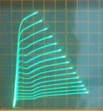
38/12/6HE7 appears closest to a 21/6HB5A tube as far as a single tube match-up of curves. Obviously not the same Pdiss though (10 Watt vs. 18 Watt). However, I found that paralleling 2X 38HE7 gives curves that exactly match with the older style 42KN6 (30 Watt Pdiss) which had two small pentodes in parallel inside. (the later single section 42/6KN6 used 33 Watt 6KD6 guts according to an RCA memo)
The 38HE7 has a datasheet pentode Pdiss rating of 10 Watts, but an obviously bigger tube section is used inside. The internal damper diode (a 6BZ3 apparently) puts out 7.5 Watts of heater power and up to 6.5 Watts of diode plate diss. Since many 38HE7 tubes have the pentode-only heater connections on pins 10 and 12, it can often be run without the damper diode (21V heater for pentode). I had estimated about 15 Watts Pdiss. allowed for the pentode a while back, which then fit perfectly with 1/2 the 30 Watt Pdiss of the early style 42KN6. (which George commented that it sounded better than the new 42KN6 version)
On dissection, the 38HE7 pentode has a slightly finer wire pitch on grid1 than the 21/6HB5A has. And the triode curves for 38HE7 are somewhat better (less roll-over) than the 21HB5A too.
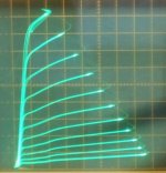
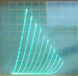
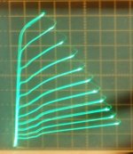
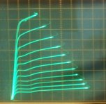
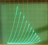
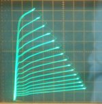
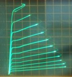
Some curves:
1) 6HJ5 in pentode
2) 6HJ5 in triode mode
3) 6DQ5 in pentode
4) 6DQ5 in triode mode
5) 38HE7 in pentode (a higher 125V required on grid2 to get the same vertical current span as the bigger tubes, so bigger kinks here)
6) 38HE7 in triode mode
7) 21HB5A in pentode
8) 21HB5A in triode mode
9) 42KN6 (old double style) in pentode
10) 21LG6A in pentode
note:
the 42KN6 and 38HE7 pentode pics here are not quite directly comparable, since the 38HE7 had 125V on g2 and the 42KN6 had 76V on g2 in order to get the same vertical current span. (so kinks are smaller on the 42KN6 plot) Also 2V g1 steps on the 38HE7 and 1V steps on the 42KN6. With two 38HE7 paralleled they match up exactly.
Most TV Sweep tubes look fairly similar anyway, mostly variation of gm1 mainly, and some variance of the screen current kinks. Also some difference in Rp slope to the pentode curves. The triode curves give the best indication of native (no Fdbk) linearity.
Reliable operation in triode mode (for TV Sweeps) is not guaranteed by these curves, as some may develop bias run-away with high grid 2 voltages over time.
38/12/6HE7 appears closest to a 21/6HB5A tube as far as a single tube match-up of curves. Obviously not the same Pdiss though (10 Watt vs. 18 Watt). However, I found that paralleling 2X 38HE7 gives curves that exactly match with the older style 42KN6 (30 Watt Pdiss) which had two small pentodes in parallel inside. (the later single section 42/6KN6 used 33 Watt 6KD6 guts according to an RCA memo)
The 38HE7 has a datasheet pentode Pdiss rating of 10 Watts, but an obviously bigger tube section is used inside. The internal damper diode (a 6BZ3 apparently) puts out 7.5 Watts of heater power and up to 6.5 Watts of diode plate diss. Since many 38HE7 tubes have the pentode-only heater connections on pins 10 and 12, it can often be run without the damper diode (21V heater for pentode). I had estimated about 15 Watts Pdiss. allowed for the pentode a while back, which then fit perfectly with 1/2 the 30 Watt Pdiss of the early style 42KN6. (which George commented that it sounded better than the new 42KN6 version)
On dissection, the 38HE7 pentode has a slightly finer wire pitch on grid1 than the 21/6HB5A has. And the triode curves for 38HE7 are somewhat better (less roll-over) than the 21HB5A too.
Some curves:
1) 6HJ5 in pentode
2) 6HJ5 in triode mode
3) 6DQ5 in pentode
4) 6DQ5 in triode mode
5) 38HE7 in pentode (a higher 125V required on grid2 to get the same vertical current span as the bigger tubes, so bigger kinks here)
6) 38HE7 in triode mode
7) 21HB5A in pentode
8) 21HB5A in triode mode
9) 42KN6 (old double style) in pentode
10) 21LG6A in pentode
note:
the 42KN6 and 38HE7 pentode pics here are not quite directly comparable, since the 38HE7 had 125V on g2 and the 42KN6 had 76V on g2 in order to get the same vertical current span. (so kinks are smaller on the 42KN6 plot) Also 2V g1 steps on the 38HE7 and 1V steps on the 42KN6. With two 38HE7 paralleled they match up exactly.
Most TV Sweep tubes look fairly similar anyway, mostly variation of gm1 mainly, and some variance of the screen current kinks. Also some difference in Rp slope to the pentode curves. The triode curves give the best indication of native (no Fdbk) linearity.
Reliable operation in triode mode (for TV Sweeps) is not guaranteed by these curves, as some may develop bias run-away with high grid 2 voltages over time.
Attachments
-
 rsz_6hj5_p.jpg50.6 KB · Views: 579
 -
 rsz_6hj5_t.jpg36.4 KB · Views: 563
 -
 rsz_26dq5_p.jpg64.2 KB · Views: 566
 -
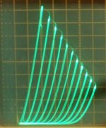 rsz_26dq5_t.jpg60.9 KB · Views: 532
 -
 rsz_38he7_p_50_50_1p5vstep.jpg76 KB · Views: 49
 -
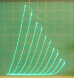 rsz_38he7_50_50_8_triode.jpg57.5 KB · Views: 57
 -
 rsz_21hb5a_p.jpg50.3 KB · Views: 55
 -
 rsz_21hb5a_t.jpg44.9 KB · Views: 52
 -
 rsz_42kn6_p_50_50_76v_1vstp.jpg83.6 KB · Views: 49
 -
 rsz_21lg6_p.jpg44 KB · Views: 54
Last edited:
- Home
- Amplifiers
- Tubes / Valves
- Those Magnificent Television Tubes