I was just about to start wiring when I noticed this...
A picture is worth a thousand words, so there's a pic attached.
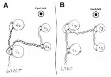
Is "A" a really wrong way to wire up four tube sockets for parallel AC heaters?
Is "B" the only way it should be done?
The problem I have is that I would like to put an input jack right above ("north" of) V3, but I'm worried about the heater twisted pair passing right near the back of that jack.
Or should I be more worried about the "open" ends of the heaters on V2 and V3 in "A", which would expose the input jack to the AC field?
A picture is worth a thousand words, so there's a pic attached.
Is "A" a really wrong way to wire up four tube sockets for parallel AC heaters?
Is "B" the only way it should be done?
The problem I have is that I would like to put an input jack right above ("north" of) V3, but I'm worried about the heater twisted pair passing right near the back of that jack.
Or should I be more worried about the "open" ends of the heaters on V2 and V3 in "A", which would expose the input jack to the AC field?
Attachments
The most important thing is to try and minimize the untwisted loop area around the sockets and either case as shown seems to do this fine.
Personally I prefer A as it would slightly reduce the filament voltage drop to the remaining two tubes - probably not enough to be worth worrying about.
The only real issue IMHO is not to put too many wires on the socket pins such that they are not mechanically solid prior to soldering. (How many of us have done/do that... Guilty.. )
)
Personally I prefer A as it would slightly reduce the filament voltage drop to the remaining two tubes - probably not enough to be worth worrying about.
The only real issue IMHO is not to put too many wires on the socket pins such that they are not mechanically solid prior to soldering. (How many of us have done/do that... Guilty..
)Thanks to all!
Fortunately, V1 and V2 are octal sockets with nice, hefty solder tabs.
V3 and V4 are 9-pin minis. There will be 900mA going to that branch.
Also, that input jack may be a balanced 1/4" phone jack (nice old Switchcraft part). That should reject hum well too.
I'm glad I can do "A". I was hoping that would be the consensus.
--
Thanks to all!
Fortunately, V1 and V2 are octal sockets with nice, hefty solder tabs.
V3 and V4 are 9-pin minis. There will be 900mA going to that branch.
Also, that input jack may be a balanced 1/4" phone jack (nice old Switchcraft part). That should reject hum well too.
I'm glad I can do "A". I was hoping that would be the consensus.
--
You won't get much hum resistance from the jack if its on this side of the topplate.
To get significant results in shielding input wires,
try using a mini-coaxial cable from the jack right to the first input tube, and star ground that shield to a good central ground around the early stage(s). Then floating the jack will be significant.
For the heaters, physical layout is critical:
BAD LAYOUT:
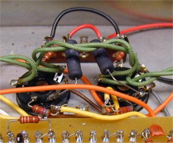
BETTER LAYOUT:
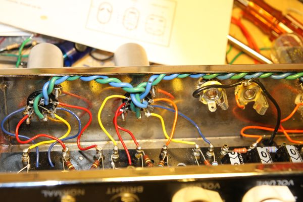
COMPONENTS WELL AWAY FROM AND AT RIGHT ANGLES TO HEATERS
Last edited:
Thanks for the tips. I think my wiring is not so bad as the first picture. That's pretty wretched.
I'm not sure if it was clear from what I wrote, but I was thinking of making the input to this amp fully balanced, as in push-pull differential. That's what the 3-conductor phone plug would be used for. I know XLR's would be way better, but I already have the cables made up. And really, how bad are 3-conductor 1/4" compared to (yeesh) RCA phono connectors?
--
- Status
- This old topic is closed. If you want to reopen this topic, contact a moderator using the "Report Post" button.
- Home
- Amplifiers
- Tubes / Valves
- Silly basic layout question - AC heaters