http://www.triodeel.com/images/b9b.gif
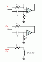
The filters for this EQ look like a type of gyrator. Does anyone know the equations on how to calculate the resistor and capacitor values based off of Fc and Q?
The only reliable gyrator source I was able to find used opamps which are easy enough to work with, but nothing for tubes.
The filters for this EQ look like a type of gyrator. Does anyone know the equations on how to calculate the resistor and capacitor values based off of Fc and Q?
The only reliable gyrator source I was able to find used opamps which are easy enough to work with, but nothing for tubes.
The inverting and non inverting inputs are both used.
http://upload.wikimedia.org/wikipedia/commons/1/16/Op-Amp_Gyrator.svg
http://upload.wikimedia.org/wikipedia/commons/1/16/Op-Amp_Gyrator.svg
Last edited:
thought I had seen another thread
http://www.diyaudio.com/forums/tubes-valves/210700-tone-controls.html
http://www.diyaudio.com/forums/tubes-valves/210700-tone-controls.html
Both inputs are shown as being used, and the diagram is a bit ic specific. The op-amp is wired as a unity gain voltage follower, with hi-z in, lo-z out.
Perhaps this might help:

The voltage follower can be implemented with valves, transistors or ic op-amps. This also applies to operational amplifiers.
Perhaps this might help:

The voltage follower can be implemented with valves, transistors or ic op-amps. This also applies to operational amplifiers.
Guitar Pedals: Gyrator Filter Calculator
I found a calculator here for determining the values of the center frequency and Q factor. Anyone know what the equations are?
I know that:
- The amplifier, R, and C substitute for an inductor. Each inductor has a Q factor. This can obviously be influenced by R and C for a synthetic inductor.
- RL is the series resistor for the inductor substitute.
- center frequency = BQ
- L = Rl * R * C
- Status
- This old topic is closed. If you want to reopen this topic, contact a moderator using the "Report Post" button.