Oh my God! I had a revelation this morning when I thought about how the AC signal sees the load. I always try to think in AC current loops to understand what is going on in a schematic. Until now I couldnt quite understand the LTP, CCS or not.
I thought about how the currents flow and then it became clear.
So I sat down and started drawing. The cool thing is that everything is explained now, and measurements correlate with calculations. Here is what I came up with:
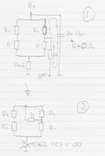
First the standard LTP with only CCS in tail.
Drawing 1 (step 1+2):
Ra is Ranode; the external resistor connected between plate and B+.
Ri is internal resistance of tube (plate/anode resistance (d3a->2k)
Rl is Rload.
In the drawing I try to explain that the powersupply capacitor is a shortcircuit for AC, and the tail CCS is an open circuit for AC.
Drawing 2 (step 3):
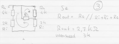
Here you can clearly see both current loops; Ra parallel to Rload, parallel to Ri+Ri+Ra. Output impedance with Ri=2K and Ra=4K is 2.7K. I measured 2.7K")
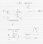
Now the CCS version:
Drawing 3 (step 4+5)
I try to explain that Ra is now a CCS, wich is an open circuit for AC.
As you can see in step 5, There is no current loop any more, it is an open circuit, so output impedance is infinite. Because I used the current spilling resistors in my real schematic, and the CCS's aren't perfect, I measured 30K.
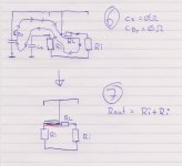
Drawing 4 (step 6+7)
As proposed by Michael Koster and Godfrey, I added Cx from the - output to ground. As Cx and the powersupply capacitor are both shortcircuits to AC, I drew the current loop, and that led to step 7, with the extra capacitor Cx marked with green and red. Essentialy it closed the current loop.
Rout is now Ri+Ri: 2K+2K-> 4Kohm. I measured 5Kohm.
I suspect that the real Ri at my chosen setting for the tube (180v Va, 15mA)
is closer to 2.5K.
Anyway, it looks like it explaines everything I measured.
Please take a look at it, and let me know if i'm on the right track!
Or not
Paul
I thought about how the currents flow and then it became clear.
So I sat down and started drawing. The cool thing is that everything is explained now, and measurements correlate with calculations. Here is what I came up with:
First the standard LTP with only CCS in tail.
Drawing 1 (step 1+2):
Ra is Ranode; the external resistor connected between plate and B+.
Ri is internal resistance of tube (plate/anode resistance (d3a->2k)
Rl is Rload.
In the drawing I try to explain that the powersupply capacitor is a shortcircuit for AC, and the tail CCS is an open circuit for AC.
Drawing 2 (step 3):
Here you can clearly see both current loops; Ra parallel to Rload, parallel to Ri+Ri+Ra. Output impedance with Ri=2K and Ra=4K is 2.7K. I measured 2.7K
Now the CCS version:
Drawing 3 (step 4+5)
I try to explain that Ra is now a CCS, wich is an open circuit for AC.
As you can see in step 5, There is no current loop any more, it is an open circuit, so output impedance is infinite. Because I used the current spilling resistors in my real schematic, and the CCS's aren't perfect, I measured 30K.
Drawing 4 (step 6+7)
As proposed by Michael Koster and Godfrey, I added Cx from the - output to ground. As Cx and the powersupply capacitor are both shortcircuits to AC, I drew the current loop, and that led to step 7, with the extra capacitor Cx marked with green and red. Essentialy it closed the current loop.
Rout is now Ri+Ri: 2K+2K-> 4Kohm. I measured 5Kohm.
I suspect that the real Ri at my chosen setting for the tube (180v Va, 15mA)
is closer to 2.5K.
Anyway, it looks like it explaines everything I measured.
Please take a look at it, and let me know if i'm on the right track!
Or not
Paul
Attachments
If I apply the same logic to the standard 1 CCS version, I get the following:
If I add Cx there, output impedance changes from :Ra//Ri+Ri+Ra to Ra//Ri+Ri.
Calculation of Cx looks simple to me; I suspect: Fc->10Hz = 1/ (2 x PI x (Ri+Ri) x C)
C=~4uF -> 4.7 uF should be good for -3dB below 10Hz.
Am I right?
Paul
If I add Cx there, output impedance changes from :Ra//Ri+Ri+Ra to Ra//Ri+Ri.
Calculation of Cx looks simple to me; I suspect: Fc->10Hz = 1/ (2 x PI x (Ri+Ri) x C)
C=~4uF -> 4.7 uF should be good for -3dB below 10Hz.
Am I right?
Paul
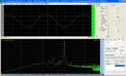
Before I forget it: Here are the distortion figures for this pre-amplifier;
It measures extremely well!
distortion at maximum output ~3v pp: 0.004% without any feedback in a single stage!
My soundcards loopback distortion is at 0.003%, so it is possible that it is even less.
I still have some work in the powersupply section, but it measures and sounds already so good, that I intend to make a thread in the digital line level forum, with all the relevant information, including all schematics.
Maybe even PCB.
It measures extremely well!
distortion at maximum output ~3v pp: 0.004%
without any feedback in a single stage!My soundcards loopback distortion is at 0.003%, so it is possible that it is even less.
I still have some work in the powersupply section, but it measures and sounds already so good, that I intend to make a thread in the digital line level forum, with all the relevant information, including all schematics.
Maybe even PCB.
Attachments
I found out some interesting facts:
The noise in the 3 CCS version was coming from the top CCS (10m45s)
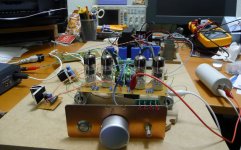
I just made a shunt powersupply with a 10m45s, and before I connected a capacitor to ground from the output, I had the same noise (hiss) as the 3 CCS LTP.
After the capacitor was placed, the pre-amp was dead quiet, no noise and no hum.
But i'm still thinking about a good actively regulated powersupply instead of the passive c-r-c-r-c-r-c. If only I could get LT3080, I would use the "21 century Maida Regulator" from Tomchr:
http://www.diyaudio.com/forums/tubes-valves/209067-21st-century-maida-regulator.html
2nd thing I found out:
Remember the capacitor that Michael Koster and Godfrey advised? (from the second output (-) to ground)
In the 3 CCS version it dropped the noise, hum and output impedance and increased gain, but I did no distortion measurements, because it sounded less good.
Now with the standard 1 ccs version, I decided to give that same capacitor a try, as I thought it would lower output impedance a bit, and maybe decrease hum.
After connecting it DID reduce hum, but again it sounded "less".
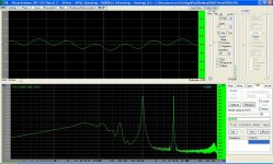
Then I decided to measure distortion, and what do you think:
Without capacitor: some hum but distortion ~0.005%
With capacitor: Far less hum BUT distortion rose to ~0.04%! that is almost 10 times as much! It was mostly 2nd order and a little third.
So maybe my ears arent so bad as I feared
The noise in the 3 CCS version was coming from the top CCS (10m45s)
I just made a shunt powersupply with a 10m45s, and before I connected a capacitor to ground from the output, I had the same noise (hiss) as the 3 CCS LTP.
After the capacitor was placed, the pre-amp was dead quiet, no noise and no hum.
But i'm still thinking about a good actively regulated powersupply instead of the passive c-r-c-r-c-r-c. If only I could get LT3080, I would use the "21 century Maida Regulator" from Tomchr:
http://www.diyaudio.com/forums/tubes-valves/209067-21st-century-maida-regulator.html
2nd thing I found out:
Remember the capacitor that Michael Koster and Godfrey advised? (from the second output (-) to ground)
In the 3 CCS version it dropped the noise, hum and output impedance and increased gain, but I did no distortion measurements, because it sounded less good.
Now with the standard 1 ccs version, I decided to give that same capacitor a try, as I thought it would lower output impedance a bit, and maybe decrease hum.
After connecting it DID reduce hum, but again it sounded "less".
Then I decided to measure distortion, and what do you think:
Without capacitor: some hum but distortion ~0.005%
With capacitor: Far less hum BUT distortion rose to ~0.04%! that is almost 10 times as much! It was mostly 2nd order and a little third.
So maybe my ears arent so bad as I feared
Last edited:
The shunt powersupply from the previous post was an attempt to lower hum AND maintain low distortion figures. It succeeded, no noise, no hum (at least much less then my SE poweramp wich has some residual hum if your ear is near the speaker.)
And the distortion stays the same low 0,005%.
What did I learn:
-CCS 10m45s can be noisy
-Somethimes at first glance some improvements (less hum and noise) arent improvements at all (more distortion)
- Trust my ears!
I wonder if there are still some people reading this thread
Paul
And the distortion stays the same low 0,005%.
What did I learn:
-CCS 10m45s can be noisy
-Somethimes at first glance some improvements (less hum and noise) arent improvements at all (more distortion)
- Trust my ears!
I wonder if there are still some people reading this thread
Paul
I think this is going to be the last post in a while; results so far:
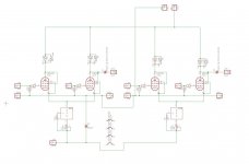
-Latest schematic attached (stereo)
-THD 1kHz ~0.005%
-Gain ~23x: Buffalo3 DAC 8mA into 2x4.7ohm= vout pp 1.68v
-Output impedance ~3Kohm
-CMRR excellent (just tested)
-PSRR not so good; needs regulated power supply
Things to do:
-Change I/V resistors from simple metal film to shinkoh tantalum.
-Increase I/V resistors to 10ohms to increase output to ~3.5v pp.
-Evaluate different power supplies.
-Build some nice enclosures; 1 for DAC preamp, and 1 for powersupply.
Attachments

Last edited:
Hi Paul,
Fascinating thread, thank you! I too have a Buffalo IIISE and am looking to experiment further with balanced valve output stages. I am currently using a tube-i-zator (http://www.diyaudio.com/forums/group-buys/156149-tube-i-zator-professional-pcb.html) but want to try something other than a SRPP circuit - as they get a lot of flack on DIYA and other places and I want to compare it to something.
Did you progress further with this project and if so could you post an updated schematic, or do you have any other suggested circuits that I coud research?
Cheers,
Crom
Hi Crom,
Still not completely finished... mostly lazyness on my side. Hope to do something again in de dark days to come. In the summer i tried to spend as much time as possible outside...enjoying the sun.
The schematic hasnt changed at all; I only added a regulated shunt powersupply. I increased the i/v resisters to shinkoh 10 ohm, because thats the lowest i could get my hands on. Havent heard them tough....Have to reassemble. The enclosure took a lot of time....
Paul,
Any news ?
I have build a very similar setup, but used 4p1l and OPT LL1692a plus dual mono-Bufallos...will work next on the PSU a bit more...by the way: TX2575 sounded nest to me in I/V...the shinkoh are a bit nice, but dull sounding, less resolution.
I am trying to understand how Browskie's Unbalancer two would sound...vertical differential amp as he calls it...
The 4p1l has a very authentic, but soft sound, you hear less hifi and more music...nice.
- Status
- This old topic is closed. If you want to reopen this topic, contact a moderator using the "Report Post" button.
- Home
- Amplifiers
- Tubes / Valves
- I need help with ccs based LTP