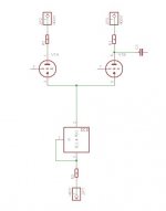
First schematic attached is a standard LTP; it is a great differential gain stage, and if you use only one output, also a great differential-to-SE converter.
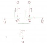
Second schematic is a LTP with CCS's in the tail and the anode circuits. Normally the problem with this schematic is that it it nearly impossible to set the currents right. The current set for the top ccs should be exact 50% of that for the cathode ccs. I tried to solve it with setting the top ccs'es for a little bit more then 50% and a bleeder resistor to bleed the extra current to ground.
But my real question is: does it stil function as a differential amplifier?
I fear not; the current in the tail looks to me as always 50% triode A and 50% triode B. So I fear that it behaves more or less as two separate stages.
Am I right?
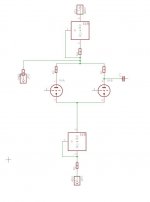
Third schematic is a possible solution; but has it advantages over schematic 1, or am I making it unnecessary difficult for myself?
What I would try to accomplish is a better PSRR; I need only a few mV swing.
Second schematic is a LTP with CCS's in the tail and the anode circuits. Normally the problem with this schematic is that it it nearly impossible to set the currents right. The current set for the top ccs should be exact 50% of that for the cathode ccs. I tried to solve it with setting the top ccs'es for a little bit more then 50% and a bleeder resistor to bleed the extra current to ground.
But my real question is: does it stil function as a differential amplifier?
I fear not; the current in the tail looks to me as always 50% triode A and 50% triode B. So I fear that it behaves more or less as two separate stages.
Am I right?
Third schematic is a possible solution; but has it advantages over schematic 1, or am I making it unnecessary difficult for myself?
What I would try to accomplish is a better PSRR; I need only a few mV swing.
Attachments
Yes, with high value resistors from anodes to ground it should work well and give good PSSR. The third circuit should work OK too, but I think I prefer the second one. YMMVSecond schematic .... does it stil function as a differential amplifier?

First schematic attached is a standard LTP; it is a great differential gain stage, and if you use only one output, also a great differential-to-SE converter.
Second schematic is a LTP with CCS's in the tail and the anode circuits. Normally the problem with this schematic is that it it nearly impossible to set the currents right. The current set for the top ccs should be exact 50% of that for the cathode ccs. I tried to solve it with setting the top ccs'es for a little bit more then 50% and a bleeder resistor to bleed the extra current to ground.
But my real question is: does it stil function as a differential amplifier?
I fear not; the current in the tail looks to me as always 50% triode A and 50% triode B. So I fear that it behaves more or less as two separate stages.
Am I right?
Third schematic is a possible solution; but has it advantages over schematic 1, or am I making it unnecessary difficult for myself?
What I would try to accomplish is a better PSRR; I need only a few mV swing.
It might help to realize that there is no conceptual difference between #1 and #2 - only a difference in quantities. If in #1 you increase the supply voltage and the anode load inpedance you get closer and closer to #2. #2 allows you to have a very high anode load impedance but with a reasonable anode voltage. Not fundamentally different from #1.
jan didden
As has been suggested, you want a high but matching impedance in the anodes of #2, I think it's best to use a stiff CCS so this is easily definable with 1% resistors in parallel (220k sounds like a good value, I think much higher than that then you're at the whim of various leakage capacitance to set things off balance)
In fact, I think gyrators would be better suited for the upper loads (in parallel with high value resistors), I think this would make the DC operating point a bit more predictable. You'd even be able to set the plate voltages independently, or even adjust for the same current (via plate voltage) through each half.
I have a lot of 10M45S in my partsbin; I would like to use them for this.
Since most of you seem to prefer v2, i'm going to use that. Could I run into problems because they are all equally "stiff"?
@bigwill: I think I can use the bleeder-resistors to set the plate voltage. If I send say 2mA through them; I can choose the value of them so that I get the wanted plate voltage.
Thanks for all your replies so far!
Paul
No !First schematic attached is a standard LTP; it is a great differential gain stage, and if you use only one output, also a great differential-to-SE converter.
Second schematic is a LTP with CCS's in the tail and the anode circuits. Normally the problem with this schematic is that it it nearly impossible to set the currents right. The current set for the top ccs should be exact 50% of that for the cathode ccs. I tried to solve it with setting the top ccs'es for a little bit more then 50% and a bleeder resistor to bleed the extra current to ground.
But my real question is: does it stil function as a differential amplifier?
I fear not; the current in the tail looks to me as always 50% triode A and 50% triode B. So I fear that it behaves more or less as two separate stages.
Am I right?
Even with different currents in each tube, the DIFFERENCE will always be the same.
The sum of the currents being imposed by the CCS in the cathode, individual currents in each tube will always be equal but of different polarity.
So, the stage remains purely differential as long as the load resistors remains equal regardless of the tube's caracteristics, even if the current repartition if far from 50/50 % !
But if you really bother about that, why not put a CCS allowing exactly 50% in only one anode ? The other tube will then be forced to draw the 50% remaining
") . . . more or less the variations imposed by the signal applied between the grids . . . I guess
. . . more or less the variations imposed by the signal applied between the grids . . . I guess Yves.
Mmmmh, Perhaps should I patent that ?
Pauldune,
in Morgan Jones, Valve Amplifiers, 3rd edition, p. 136 we find Fig. 2.49 which actually corresponds to your topology #2. Never got it working, though using a »stiff« CCS as tail and two less stiff CCS's as plate loads, same as in Jones's circuitry. I strongly do believe that no one ever will go with it. Determining each plate current plus determining the sum of both will never work unless we use components with zero tolerances, including both triodes.
Best regards!
Hey Kay,
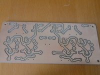
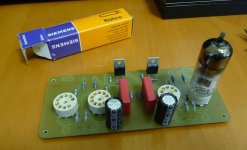
Thats why I set both anode ccs's for MORE than 50%, and bleed of the excess current, and use that current to set the anode voltage. Or at least thats the idea. Hope to test it tomorrow; i have a pcb ready for schematic 1 that I can use as a base of experimentations.
(is that good english?)
I will try all topologies, and measure distortion psrr and so on... Then I will post it here.
Attachments
Last edited:
Hey Kay,
Thats why I set both anode ccs's for MORE than 50%, and bleed of the excess current, and use that current to set the anode voltage. Or at least thats the idea. Hope to test it tomorrow; i have a pcb ready for schematic 1 that I can use as a base of experimentations.
(is that good english?)
I will try all topologies, and measure distortion psrr and so on... Then I will post it here.
At least I do understand you ;-)!
Regardless whether you set the anode CCS's for more or less than 50% of the total current and bleed the excess by resistors paralleled either to the triodes or the anode CCS's respectively, this does mean that you reduce the CCS's impedance more or less dramatically - and at the same time their necessity.
Best regards!
Yes, but....
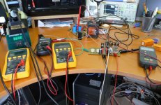
I just measured schematic 1 and 3, and the difference in PSRR is dramatic.
The psrr without ccs in the anode line is zero (0); output ripple was the same as power supply ripple. (about 500mV pp)
with one ccs directly below V+ and a bleeder of 110kohm (like schematic 3) , I measured output ripple about 20mV.
I made one mistake on my pcb; 10K 1/4 watt resistor with 20mA current= smoke! (4watt dissipation)
Attachments

At least I do understand you ;-)!
Regardless whether you set the anode CCS's for more or less than 50% of the total current and bleed the excess by resistors paralleled either to the triodes or the anode CCS's respectively, this does mean that you reduce the CCS's impedance more or less dramatically - and at the same time their necessity.
Best regards!
It's a bad idea to use CCS's in the anode line and then NOT use some form of feedback to set the anode voltage. As you guys probably found, that's almost impossible to predict!
With some form of feedback to set Va they work great but open loop you keep on tweaking and then will find that they still run away with aging, temp and tolerances.
Some things are not meant to be
jan
OK one step further! The 50Khz isnt oscillation!
I switched back to the other two schematics, only to find the exact same rubbish.
So I removed the testleads of the multimeter, only to find they were picking up the 50kHz.
I then went back to the 3 CCS version, and it works OK now! I had some 50Hz with strange spikes on the output, but it was the heater; I still run it with AC, and hadn't connect it to ground. Now I centered it around GND with 2x 1Kohm resistors, and the hum is almost gone.
I will try a DC heater soon.
I have to measure the distortion some other time....i've had enough for now
@Jan: Isnt the bleeder resistor a kind of stabilizer? The current through it keeps it at a constant voltage... Also it looks stable to me, after 1 hour of running the voltages measured are within 5 volts of the value I set them, and I dont see any changes anymore.
- Status
- This old topic is closed. If you want to reopen this topic, contact a moderator using the "Report Post" button.
- Home
- Amplifiers
- Tubes / Valves
- I need help with ccs based LTP