Just did some measurements:
Gain: 35x SE (so that is +/- 70x with a differential input)-> nice!
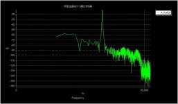
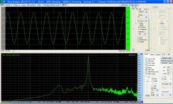
Distortion: ~ 0.01%-0.02%; see FFT attached-> really nice! I had some troubles with the EMU 0202; output noise was a little to high, but in the end i'm not disappointed.
Things to do:
-Measure distortion with the differential dac connected to the input, and a test CD.
-Build a DC heater.
-Redesign PCB.
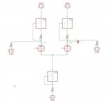
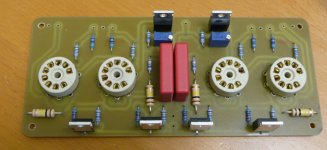
The schematic is as attached; component values:
R1=R2=100 Ohm, 1/4W, metalfilm 1%
R3= adjustable 100 Ohm; now set for 48 ohm. adjust it so Vanode/plate is 160v (beware I made a mistake in the drawing, pin 1 of lower ccs should be connected under R3)
I used 1Kohm gridstoppers on tubes and CCS's.
R4=R5=100Kohm, 1W, metalfilm 1%
Gain: 35x SE (so that is +/- 70x with a differential input)-> nice!
Distortion: ~ 0.01%-0.02%; see FFT attached-> really nice! I had some troubles with the EMU 0202; output noise was a little to high, but in the end i'm not disappointed.
Things to do:
-Measure distortion with the differential dac connected to the input, and a test CD.
-Build a DC heater.
-Redesign PCB.
The schematic is as attached; component values:
R1=R2=100 Ohm, 1/4W, metalfilm 1%
R3= adjustable 100 Ohm; now set for 48 ohm. adjust it so Vanode/plate is 160v (beware I made a mistake in the drawing, pin 1 of lower ccs should be connected under R3)
I used 1Kohm gridstoppers on tubes and CCS's.
R4=R5=100Kohm, 1W, metalfilm 1%
Attachments
Hi Kay,
What is a current mirror? Same as a CCS?
I tried the schematic with the 3 ccs's directly connected to the differential current output from a DAC, and it works perfect! Direct connected; so no caps on the input; just one on the output. Distortion is the same as above; will upload the screenshots this evening.
Paul
Ok, i get it, but what do you want them to mirror? Not the current from the other branch, i would think, because thats normally exactly the opposite.
Could you draw a simple concept? And explain what you want to accomplish?
(if you want)
Paul
Interesting thread.
In 2003 I was planning a rather elaborate amplifier and had prototyped most of it. I fancied the idea of active loads and CCS and developed the stage despite a number of folk telling me that the idea wouldn't work. See Sy's post on the first page of this thread though - I used MJE350 for the active load and the CCS was a typical Morgan Jones cascode, but without negative supply (I can't remember why), Of course the pentode loads were CCS as well. It used a 7N7 as the gain part and this was followed with a pair of E810F pentodes arranged as (pentode) cathode followers; The pentode cathode followers were intended to be DC-coupled to the output stage and therefore sat on a -280V rail.
At the time I had a reasonable collection of test gear and was able to measure distortion up to sixth harmonic, The complete stage delivered 77.5V rms into a 30k load with distortion more or less at the floor of the test gear - -64dB = 0.063%; amazingly third harmonic was at -87dB,
Of course I never used it since my circumstances changed rather radically. I still have a circuit diagram scribbled,
Paul
Last edited:
Hi Paul,
Sad to hear you couldnt use your design because of circumstances. Sometimes life doesnt play nice...
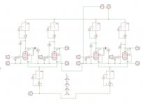
In case some of the readers are interested, i'll attach the complete schematic. I realize I haven't done that before. It is stereo, because i'm designing a stereo pcb in eagle.
Paul
Sad to hear you couldnt use your design because of circumstances. Sometimes life doesnt play nice...
In case some of the readers are interested, i'll attach the complete schematic. I realize I haven't done that before. It is stereo, because i'm designing a stereo pcb in eagle.
Paul
Attachments
Yes!4R7 on the input?

The input is a 16mA current output from a buffalo 3 dac.
Essentially the 4.7 ohm is the current to voltage converter. The buffalo needs an impedance as low as possible to get the best specs.
4.7 was the calculated value to give a maximum output of aprox. 2v out of the tube stage. Because the gain now with all the ccs's is higher as with a normal ltp, I get aprox. 3 v out. Oh and the coupling output cap isnt on the schematic because it isnt on the pcb. I have a russian teflon and a russian silvermica, i want to try wich sounds best. But both are too large to fit on the pcb.
Paul
Last edited:
Paul,
Essentially you have 100k AC load at both anodes. Without them the circuit wouldn't work, because a CCS does not permit any change in the anode current. Why don't get rid of the CCS's and connect the 100k resistors directly to the B+ ? There could be only one reason: higher bias current than with 100k load only.
Essentially you have 100k AC load at both anodes. Without them the circuit wouldn't work, because a CCS does not permit any change in the anode current. Why don't get rid of the CCS's and connect the 100k resistors directly to the B+ ? There could be only one reason: higher bias current than with 100k load only.

I dont know exactly what you mean by "positive signal tube's plate just get connected to ground" but maybe you mean the 100k from plate to ground? That is the resistor to bleed of the excess current from the top ccs.G'day Paul,
Quick question, looking at the sche, does the positive signal tube's plate just get connected to ground? Just trying to understand how the balanced signal is summed to the SE output.
What am I missing?
Thanks,
D
The top ccs is set for a few mA more than the tail ccs needs; it is nearly impossible to set both top ccs's to EXACTLY half the tail current.
So I set it for a few mA more than needed and give the current wich is too much an escape path.
A LTP is -as far as I know- a summing amplifier stage. If you connect one of the inputs to ground, it still works as an amplifier, and on both plates there is the same signal, but inverted. It is used in this way on many balanced power amplifier as phase splitter. If you attach an inverted signal to the - input, the plate signal on both plates doubles.
Wiki explaines it better then me:
Differential amplifier - Wikipedia, the free encyclopedia
Note this:
"Single-ended output:If the differential output is not desired, then only one output can be used (taken from just one of the collectors (or anodes or drains), disregarding the other output without a collector inductor; this configuration is referred to as single-ended output. The gain is half that of the stage with differential output."
D Now that I read the article to explain it to you, I see there the improved LTP with current mirror..LOL wish I saw that before...)Hi Paul,
what's in the CCS boxes? Are there LM317's or TL783's, respectively?
Best regards!
All 10M45S; it had 20 of them lying around...
And I can see clearly now that a current mirror loaded differential amplifier won't work as a phase inverter...
Best regards!
Just a thought, maybe a silly one, I've never tried it though: What about a pair of hfe/vbe-selected video pnp transistors, connected as current mirrors, as plate loads?
Best regards!
Yes Kay, now I understand what you said...
It wont work as a fase inverter, but it would work for my purpose; if its better then what I build now I dont know...
Maybe I will try it someday.
Thanks!
Paul
- Status
- This old topic is closed. If you want to reopen this topic, contact a moderator using the "Report Post" button.
- Home
- Amplifiers
- Tubes / Valves
- I need help with ccs based LTP