Hi,
I'm building a phono stage and I have question about a couple of resistors and their values.
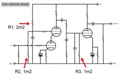
The parts list states that r1 should be 2m2 ohms and r2 and r3 should be 1m2 ohms.
I ordered Allen Bradley resistors in these values but they are all quite a bit off.
The 2m2's are all about 2m4 ohms and the 1m2 are all about 1m35 ohms.
Now for my question, what is the purpose of these resistors in the circuit and how critical are their values?
Would it be ok to use the one's I have or should I get some more accurate?
Tnx
Cj
I'm building a phono stage and I have question about a couple of resistors and their values.
The parts list states that r1 should be 2m2 ohms and r2 and r3 should be 1m2 ohms.
I ordered Allen Bradley resistors in these values but they are all quite a bit off.
The 2m2's are all about 2m4 ohms and the 1m2 are all about 1m35 ohms.
Now for my question, what is the purpose of these resistors in the circuit and how critical are their values?
Would it be ok to use the one's I have or should I get some more accurate?
Tnx
Cj
Attachments
Just to be completely pedantic... It should be 2M2 and 1M2. M = Mega (1e6); m = milli (1e-3). Sorry. Pet peeve of mine.
Now to your question. The tube with its grid connected to R1, R2 looks to be operating as a cascode. It's biased by the resistive divider formed by R1, R2. The capacitor in parallel with R2 decouples the noise of the biasing network to ground.
R3 is the grid leak resistor for the last tube. It prevents tube bias point shifts by ensuring that any grid leakage current is led to ground.
The values of R1, R2, and R3 are not critical. Modern +/-5 % tolerance resistors should work just fine here. I'm sure the circuit would work even with old +/-20 % tolerance carbon composition resistors.
Modern metal film resistors are very good and resistive up past 40 MHz (the limit of my tester). Hence, I don't see any reason to use boutique resistors. But feel free to do so if you feel like it.
I disagree with Shoog's comment about noise. It is true that the thermal noise power spectral density of a resistor is linearly proportional to its resistance. However, all the resistors in question are bypassed by capacitors. This limits the noise bandwidth. Going through the math, you'll end up with en = k*T/C (en = noise power spectral density (V/rt(Hz)), k = Boltzman's Constant (1.38E-23 J/K), T = absolute temperature (K), C = capacitance (F). So the noise is actually independent of the resistor value.
~Tom
Last edited:
Resistors exhibit Johnson noise aka thermal noise.
Thermal noise: en = 4*k*T*R
k = Boltzman's constant
T = absolute temperature (deg K)
R = resistance in Ohm
en = noise power spectral density (V/sqrt(Hz))
Thermal noise is white (uniformly distributed in frequency).
In addition, carbon composition types exhibit 1/f or "popcorn" noise. I.e. the noise is higher at lower frequencies.
There's also a term called "excess noise" which, to my knowledge, refers to noise not accounted for in thermal noise. I don't know if this excess noise is voltage dependent. I've seen it listed in resistor datasheets, so if you want to know, I suggest looking there.
I'm not aware of any noise type that would depend on the current density in the resistor. The only current-dependent noise types I know of relate to the flow of carriers across a semiconductor junction. There are no semiconductor junctions in a resistor.
~Tom
As tomchr says, the resistors are bypassed (R1,2) or connected to lower impedances (R3) so their noise should not be a problem. Noise from other resistors (e.g. anode load, RIAA network) will be more important.
The exact value of R1 and R2 does not matter; it is their ratio which sets the grid voltage for the upper valve. The value of R3 will have a small effect on the LF response of the RIAA network, depending on the network impedance.
The exact value of R1 and R2 does not matter; it is their ratio which sets the grid voltage for the upper valve. The value of R3 will have a small effect on the LF response of the RIAA network, depending on the network impedance.
In addition, carbon composition types exhibit 1/f or "popcorn" noise. I.e. the noise is higher at lower frequencies.
There's also a term called "excess noise" which, to my knowledge, refers to noise not accounted for in thermal noise. I don't know if this excess noise is voltage dependent. I've seen it listed in resistor datasheets, so if you want to know, I suggest looking there.
I'm not aware of any noise type that would depend on the current density in the resistor. The only current-dependent noise types I know of relate to the flow of carriers across a semiconductor junction. There are no semiconductor junctions in a resistor.
This is all correct per modern usage. Excess noise includes all noises not accounted for by either thermal/Johnson/Nyquist noise or shot noise (current dependent noise across a potential difference), and includes popcorn, 1/f and other process-dependent noises.
There's a lot of confusion about these nowdays because older texts, RDH4 ("the big red bible") in particular, used "shot noise" to mean the thermal noise within electron valves. Causes no end of confusion these days. And "excess noise" was just as mysterious then as now!
Thanks,
Chris
This is all correct per modern usage. Excess noise includes all noises not accounted for by either thermal/Johnson/Nyquist noise or shot noise (current dependent noise across a potential difference), and includes popcorn, 1/f and other process-dependent noises.
I'm not clear on how shot noise would show up in resistors, though. There shouldn't be any potential barriers, only a linear decrease in potential across the resistor. At least in the ideal world. Do potential differences arise due to work function differences between the end caps and the resistive film material? Trying to learn here...
~Tom
I'm not clear on how shot noise would show up in resistors, though. There shouldn't be any potential barriers, only a linear decrease in potential across the resistor. At least in the ideal world. Do potential differences arise due to work function differences between the end caps and the resistive film material?
Shot noise shouldn't appear in resistors. I didn't mean to imply that, but maybe my poor wording included it. There may be some folks in the world that understand the fine line between potential differences in the separate components of a resistor and the whole resistor, and can parse the measurable differences of real-world resistors, but they don't include me. Carbon comp resistors are often described as a stack of granules, giving one pause, but I wonder how realistic that is.
My post was really just to affirm your choice of terms. Old usages cause lots of current confusion.
Thanks,
Chris
")
Shot noise shouldn't appear in resistors.
We're on the same page then.
Carbon comp resistors are often described as a stack of granules, giving one pause, but I wonder how realistic that is.
That image came to mind for me as well. But as long as the contact between the individual granules is ohmic, the potential should still decrease gradually through the resistor, hence, no shot noise should appear.
~Tom
Just a random observation;
All of the (older) carbon comp resistors I have dissected have had a solid 'pellet' of carbon inside.(the actual resistive element)
AFAICT,it seems it's just some sort of carbon powder,pressed into pellet form somehow. Something like a pencil lead,but varying in size for the given wattage.(edit: desired resistance probably plays a role in size too.)
Last edited:
If all the resistors measure 10% high, maybe the error's in the meter.The 2m2's are all about 2m4 ohms and the 1m2 are all about 1m35 ohms.
- Status
- This old topic is closed. If you want to reopen this topic, contact a moderator using the "Report Post" button.
- Home
- Amplifiers
- Tubes / Valves
- purpose and value importance of resistor