Determining the reason for mystery? cap in schematic.
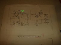
In a parallel thread I started off about the problems I encountered wiring in a volume pot, a question put to me during the course of the thread was: the purpose of a cap (circled in green) on the attached schematic that came with this little SET amp I am attempting to troubleshoot. I checked and it`s not a mistake as they are definitely wired in this way on both my EL84s
If I can`t even wire in a simple pot then you can imagine how far over my head this question is.
So any ideas on the purpose of this .001 cap between Pin 7 of the EL84 and B+..?
And of course, if anything jumps out at anyone regarding this particular schematic as being particularly problematic or improperly executed I`d be interested in your observations and suggestions.
Thks in advance. Leon
Attachments
Last edited:
Hi devilsindetails
It's a bit hard to make out in that scan but it appears to be conected between anode of output tube and B+ supply.
My best guess would be to stop some high frequency oscillation.
It could have been connected from the anode to ground but would require a higher voltage cap. Maybe done for cost reasons.
Correct! It prevents the EL from oscillating.
Thanks to you both, now I can return to regular programming and continue troubleshooting my SE EL84...as well as answer the question with proper attribution to both of you, of course.
Just for my own curiosity...if this cap (which presently is one of those small clay-orange ceramic discs) were off spec...ie: bad...any idea of what the sonic signature (symptom) would be?) High pitched squeal?
As I am replacing the caps in this amp I imagine I shouldn`t be sloppy
and ensure I replace these as a matter of course as well?Hi devilsindetails
It's a bit hard to make out in that scan but it appears to be conected between anode of output tube and B+ supply.
My best guess would be to stop some high frequency oscillation.
It could have been connected from the anode to ground but would require a higher voltage cap. Maybe done for cost reasons.
Thanks Biblio...
Oscillation probably outside of audible range.
Possible effects could be overheating of the tube and maybe some audible distortion.
Maybe even interference with AM radio reception if frequency high enough.
Ceramic caps are pretty reliable but replace them if you feel more comfortable.
Possible effects could be overheating of the tube and maybe some audible distortion.
Maybe even interference with AM radio reception if frequency high enough.
Ceramic caps are pretty reliable but replace them if you feel more comfortable.
Last edited:
Oscillation probably outside of audible range.
Possible effects could be overheating of the tube and maybe some audible distortion. Ceramic caps are pretty reliable but replace them if you feel more comfortable.
Thanks...your answer may have helped me identify why one of the 84s was running hotter than the other after I replaced all the caps (the exception being these little buggers)
Could be a tube problem.
Try swapping it with the other channel and see if the problem moves.
Yes...I was thinking ahead of myself...I was running the tubes earlier in the same amp prior to the larger capacitor renewal I undertook and both tubes were behaving equally...after my cap job one was running hotter...so I though perhaps it was likely because I hadn`t done ALL the caps. But yours is the best first course in troubleshooting. THKS
If you have a multimeter, measure between control grid an ground.
Normally you will see 0 Volts. If it is even a little positive, you could have a leaky coupling cap from the driver. What sort of caps did you use ?
OS Sprague Wax Caps, same voltage rating rating and value, but I guess there`s always a chance one of them is not quite up to snuff.
Excuse my inexperience but which pin is the control grid...
Last edited:
Waxed paper caps were notorious in the past for developing leakage as they aged. Some will disagree but I would use polyester.
Point well taken...I should be utilizing known good caps...however I used what I had on hand and superficially looked A-OK...how far above the original Uf value can I use safely...I`ve been told no more than 10%...I know I can use higher voltage rated caps (just not lower).
Depends on the value of the capacitor and the resistor between control grid and ground or more precisely the time constant of the two. To high on either one can lead to an effect called grid blocking or blocking distortion.
See an explanation here: Blocking Distortion
G2 is called screen grid.
I'm going off line now so I can't respond to any more questions until tomorrow but there are plenty of more qualified people than I here who can help you out.
Cheers for now.
See an explanation here: Blocking Distortion
G2 is called screen grid.
I'm going off line now so I can't respond to any more questions until tomorrow but there are plenty of more qualified people than I here who can help you out.
Cheers for now.
Last edited:
Depends on the value of the capacitor and the resistor between control grid and ground or more precisely the time constant of the two. To high on either one can lead to an effect called grid blocking or blocking distortion.
See an explanation here: Blocking Distortion
G2 is called screen grid.
OK..thanks so much for your time and courtesy Bibliophile...I can see I have my reading cut out for me...I`think I`ll stick with exact values for the caps for now but ensure they are known good and will try the poly`s as I`ve heard good things about them....Leon
The capacitor ringed in green is for 'tone correction' i.e. HF rolloff. Very common in old radio circuits, as people in the 1950s were not used to hearing much treble. In effect, it lowers the OPT HF resonance frequency. In essence, you have a pair of radio receiver audio stages.
The capacitor ringed in green is for 'tone correction' i.e. HF rolloff. Very common in old radio circuits, as people in the 1950s were not used to hearing much treble. In effect, it lowers the OPT HF resonance frequency. In essence, you have a pair of radio receiver audio stages.
Thanks for the input DF...now as this amplifier had a separate pre-amp/radio chassis with treble and bass pots (which I simply removed from the equation) would I be better advised to remove this particular capacitor to restore (raise) OPT HF resonance?
I intend to use this amplifier with only a volume pot and no frequency compensation.
- Status
- This old topic is closed. If you want to reopen this topic, contact a moderator using the "Report Post" button.
- Home
- Amplifiers
- Tubes / Valves
- Determing the reason for mystery? cap in schematic.