Re: Tube Line gain stage with pcc88 or ecc82
Hi all!
I need a schematic that I create the preamplifier (gain stage) in the stereo version, with one tube PCC88, or with ECC82 (12UX7). I have a regulated power supplies, which gives B=+240V/60mA.
This preamplifier to the output should have a maximum resistance to 2k7.
thank you
Hi all!
I need a schematic that I create the preamplifier (gain stage) in the stereo version, with one tube PCC88, or with ECC82 (12UX7). I have a regulated power supplies, which gives B=+240V/60mA.
This preamplifier to the output should have a maximum resistance to 2k7.
thank you
Both types mentioned are not especially well suited to the job of a line stage, with gain.
Types with a lower μ rate to be more satisfactory. The B+ rail you have will work with the 12AU7/ECC82. However, that type is not at all linear. Maybe CCS loaded, MOSFET buffered, and step down O/P trafo coupled will work. Trafos in the signal path always mean expense.
Types with a lower μ rate to be more satisfactory. The B+ rail you have will work with the 12AU7/ECC82. However, that type is not at all linear.
Maybe CCS loaded, MOSFET buffered, and step down O/P trafo coupled will work. Trafos in the signal path always mean expense.HiBoth types mentioned are not especially well suited to the job of a line stage, with gain.
Types with a lower μ rate to be more satisfactory. The B+ rail you have will work with the 12AU7/ECC82. However, that type is not at all linear.
This a valve premplifier with PCC88 or with 12AU7 (ECC82) means that gain up to 10x and the output resistance to 2.7 kOhm
thank you
Last edited:
The μ (amplification factor) of the 12AU7 is 20. That of the 6DJ8/ECC88 and its relatives is 33. Both types yield excessive gain, for this application. Neither tube, wired common cathode, will have the O/P impedance required.
The stated goals do not mate with the items already on hand.
The stated goals do not mate with the items already on hand.
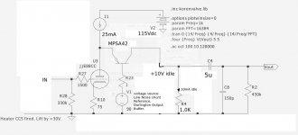
One of the range of advantages of the shunt-cascode stage is that we can decrease the 'gearing' of an amplifier: ie reduce gain AND output impedance, without sacrificing other useful parameters.
This line circuit has a gain of 10 and output impedance of 1K. it will work with any of the 1940s/50s tuner triodes that like 90-100V, including cheap PCC88 and even PCC89, if the input swing is small.
The circuit looks patched together, because I just hacked a phono stage drawing, which works and sounds superb - far better than the usual CCS loaded stages or 6SN7s etc.
Only thing to watch is that the cascode voltage of 90 -95V must be low noise and low impedance. A voltage divider with darlington buffer will suffice, but a shunt regulator is not overdoing things.
Attachments
One of the range of advantages of the shunt-cascode stage is that we can decrease the 'gearing' of an amplifier: ie reduce gain AND output impedance, without sacrificing other useful parameters.
This line circuit has a gain of 10 and output impedance of 1K. it will work with any of the 1940s/50s tuner triodes that like 90-100V, including cheap PCC88 and even PCC89, if the input swing is small.
The circuit looks patched together, because I just hacked a phono stage drawing, which works and sounds superb - far better than the usual CCS loaded stages or 6SN7s etc.Only thing to watch is that the cascode voltage of 90 -95V must be low noise and low impedance. A voltage divider with darlington buffer will suffice, but a shunt regulator is not overdoing things.
Hi Rod!
I just want to I create the pre-amp with valve / tube or PCC88 or with12UX7 (ECC82), which delivers the pleasant valve/tube sound.! Where anode voltage preamplifier range from + B=150...250V.
With the gain up to <10x and output to <2,7 kOhm!
thank you and cheers!

Last edited:
An FX box?the pleasant valve/tube sound
You have been given good advice. You need to realise that you are, in effect, asking people to tell you how to make 3=4. The tiny snag is that 3 does not equal 4, so no amount of wishing on your part can make it so.
The PCC88 will get you close on output impedance if you run it hot(high current) but you'll have 20+ gain.
If you can accept one tube per channel you could have a common cathode stage dirct coupled to a CF. Then you could tailor it to "any" gain and output impedance with some feedback.
/Olof
If you can accept one tube per channel you could have a common cathode stage dirct coupled to a CF. Then you could tailor it to "any" gain and output impedance with some feedback.
/Olof
With the gain up to <10x and output to <2,7 kOhm!
thank you and cheers!
When you say 'output <2.7K ohm' do you mean the load it is driving is 2.7K ohm or you want the output impedance to be < 2.7K ohms?
Cheers
Ian
Have a google for a jadis DPL schematic (or maybe the dpl2). It uses 12au7 and is simple enough. I know the 12au7 is frowned upon here, but I have heard one of these preamps and it sounded very good indeed. Its on my list to build one someday.
There were no special parts inside, using a 7812 for heaters.
Fran
There were no special parts inside, using a 7812 for heaters.
Fran
Output impedance is <2k7When you say 'output <2.7K ohm' do you mean the load it is driving is 2.7K ohm or you want the output impedance to be < 2.7K ohms?
Cheers
Ian
If the wrong out, please give the proposal.ehh, is out connected correctly ?
thank you
P.S.
The output is this of to reduce the gain to 10x
Last edited:
If the wrong out, please give the proposal.
thank you
Im not that clever, sorry
I just thought it looked 'different'
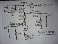
That schematic looks about right to me. Operating point is around 9mA, plate dissipation is under 1 watt. Gain should be close to 10 with that plate load pot divider. Output impedance may be higher than you desire because cathode bias resistor is not bypassed. This increases effective plate resistance from around 3K to about 10K and increases distortion.I would recommend bypassing the cathode resistor.
Cheers
Ian
Cheers
Ian
modifications
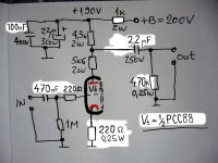
The signs of these changes on the cathode you think. Cathode to bypassing the resistor R1 = 220Ohm/0,25W and the electrolytic capacitor C1= 680uF/16V. I think that the anode current is about 11mA?.
This schematic now has as much gain and what is the output Impedance?
What is the gain without the capacitor C1?
Thanks and cheers!
P.S.
If you have another suggestion you name it.
Hi ruffrecords!That schematic looks about right to me. Operating point is around 9mA, plate dissipation is under 1 watt. Gain should be close to 10 with that plate load pot divider. Output impedance may be higher than you desire because cathode bias resistor is not bypassed. This increases effective plate resistance from around 3K to about 10K and increases distortion.I would recommend bypassing the cathode resistor.
Cheers
Ian
The signs of these changes on the cathode you think. Cathode to bypassing the resistor R1 = 220Ohm/0,25W and the electrolytic capacitor C1= 680uF/16V. I think that the anode current is about 11mA?.
This schematic now has as much gain and what is the output Impedance?
What is the gain without the capacitor C1?
Thanks and cheers!
P.S.
If you have another suggestion you name it.
Attachments
Last edited:
- Status
- This old topic is closed. If you want to reopen this topic, contact a moderator using the "Report Post" button.
- Home
- Amplifiers
- Tubes / Valves
- Re: Tube Line gain stage with pcc88 or ecc82