I have been following the on-line thread for Tube Newbies for some time in an effort to wet my theoretical feet. I've read a lot of reference books (Basic Radio Course John T. Frye GERNSBACK PUBLISHING) and the like and even picked up a thing or one, I think
I've been admonished by many to simply set about doing and building but I have to admit I don't feel comfortable or particularly competent with much of this.
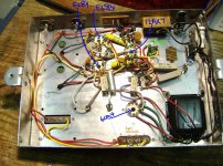
So a friend suggested utilizing an existing salvaged working two channel SE EL84 amplifier with a 12AX7 gain stage and 6CA4 tube rectifier as a means of getting my feet wet and studying the actual goings-on of a simple tube audio amplifier in action.
So now I want to take this amplifier and add one set of RCA inputs and a stereo volume pot so I can do some listening.
Adding the RCAs won't be a problem but sorting out how to hook up a stereo volume pot is.
From what I can gather I need a dual gang stereo log pot of 100K.
The wiring of the pot according to my research would be (shaft facing towards me with gang terminals at the top
1) Far right terminals inner and outer gangs: L&R Input Signal and L&R Output Signal grounds
2) Center terminals inner and outer gangs: Output Signal + leads L&R
3) Far left terminals inner and outer gangs: Input Signal + leads L&R
But where exactly do I solder the wires from the 3 terminals of each the gangs to exactly?
Lest I be accused of being lazy and not DImyselfing, or of fearing the inevitable OMG you did what! I tried valiantly to connect the pot to the amplifier but without success ie:connecting the center terminals of the gangs directly to 12AX7 pins #3 and #8 (circled in orange) OUTPUT SIGNAL and the far left terminals of the gangs to pins #2 and #6 (circled in green) INPUT SIGNAL
The pot ground connections seemed self-explanatory. I took wires from the gang ground terminals to the input audio ground and another pair to the speaker output grounds
As for the input signal connections I took wires from the gang input + terminals to the audio signal L&R + input
Several variations on the same connection theme later and I was no closer than when I started. Audio Signal? Yes! Audio Output? Yes! But maximum output and hugely distorted! A little smoke from the pot as well...
Went back to the books and tripped over some talk about no DC on pot wipers etc, paralleling resistors etc.
OK. for those who might be patient enough to assist and tolerant enough to forgive my foolhardy foray I'm all ears!
I've been admonished by many to simply set about doing and building but I have to admit I don't feel comfortable or particularly competent with much of this.
So a friend suggested utilizing an existing salvaged working two channel SE EL84 amplifier with a 12AX7 gain stage and 6CA4 tube rectifier as a means of getting my feet wet and studying the actual goings-on of a simple tube audio amplifier in action.
So now I want to take this amplifier and add one set of RCA inputs and a stereo volume pot so I can do some listening.
Adding the RCAs won't be a problem but sorting out how to hook up a stereo volume pot is.
From what I can gather I need a dual gang stereo log pot of 100K.
The wiring of the pot according to my research would be (shaft facing towards me with gang terminals at the top
1) Far right terminals inner and outer gangs: L&R Input Signal and L&R Output Signal grounds
2) Center terminals inner and outer gangs: Output Signal + leads L&R
3) Far left terminals inner and outer gangs: Input Signal + leads L&R
But where exactly do I solder the wires from the 3 terminals of each the gangs to exactly?
Lest I be accused of being lazy and not DImyselfing, or of fearing the inevitable OMG you did what! I tried valiantly to connect the pot to the amplifier but without success ie:connecting the center terminals of the gangs directly to 12AX7 pins #3 and #8 (circled in orange) OUTPUT SIGNAL and the far left terminals of the gangs to pins #2 and #6 (circled in green) INPUT SIGNAL
The pot ground connections seemed self-explanatory. I took wires from the gang ground terminals to the input audio ground and another pair to the speaker output grounds
As for the input signal connections I took wires from the gang input + terminals to the audio signal L&R + input
Several variations on the same connection theme later and I was no closer than when I started. Audio Signal? Yes! Audio Output? Yes! But maximum output and hugely distorted! A little smoke from the pot as well...
Went back to the books and tripped over some talk about no DC on pot wipers etc, paralleling resistors etc.
OK. for those who might be patient enough to assist and tolerant enough to forgive my foolhardy foray I'm all ears!
Attachments
Last edited:
Hi,
Smoke on pot? Bit concerning. Measure the dc voltage between wiper and ground. For safety reasons put a capacitor between input terminal and pot input terminal and try again.
Your problem sounds to me a high dc content on your signal source. What signal source do you use anyway? Can you post the schematics?
Hope this will help you a bit.
Stef.
Thanks. I used a CD player for signal source. Sorry no schematic. Should I simply forget the volume pot right now and see what kind of output signal I get SANS volume pot?Hi,
Smoke on pot? Bit concerning. Measure the dc voltage between wiper and ground. For safety reasons put a capacitor between input terminal and pot input terminal and try again.
Your problem sounds to me a high dc content on your signal source. What signal source do you use anyway? Can you post the schematics?
Hope this will help you a bit.
Stef.
Pins 3 and 8 are the cathodes, you want pins 2 and 7 which are the grids. Signal grounds should not be at the speaker terminals, but at the input tube (12AX7) grounds.
OK so pins 2 & 7 are for signal input and 3 & 8 are for amplified signal output Yes?
Thanks for the advice on the grounds. You are talking about both input and ouput signal grounds to 12AX7 grounds?
Last edited:
Does your CD player have an output level control? If so that may work satisfactorily. If it does not, it will be extremely loud and distorted.Thanks. I used a CD player for signal source. Sorry no schematic. Should I simply forget the volume pot right now and see what kind of output signal I get SANS volume pot?
Looking down at the pot with the shaft pointing towards you:
RI RO G
LI LO G
Where as:
RI=Right Input
RO=Right Output
G=Ground
LI=Left Input
LO=Left Output
G=Ground
The grounds from the RCA jacks and the output signal grounds should be connected to the same terminal on the pot, then to the grounds located at the input tube socket where the 2.2k resistors (Red, Red, Red) connect to ground.Yes You are right of course....I can't even count the pins correctly...they were connected to 2 & 7. Thanks for the advice on the grounds. You are talking about ouput signal grounds correct?
Last edited:
Another thing: use screened wiring for the input signal. I was looking closer at your image, the heater wire of the 12AX7 crosses the input wire to the grid. I can't see a grid stopper resistor on the grids of the 12AX7 either. Just connect a 1MOhm resisror from grid to ground as close as possible to the tube base.
If the pot "smoked" then you may have inadvertently connected it to a voltage source. Hopefully the pot is still good but it may not be as you may have fried it, sorry! Be careful as there are a few hundred volts on some pins of the input tube socket, namely pin 1 and pin 6, which are the plates (anodes). 4, 5 and 9 are the filament connections.

Another thing: use screened wiring for the input signal. I was looking closer at your image, the heater wire of the 12AX7 crosses the input wire to the grid. I can't see a grid stopper resistor on the grids of the 12AX7 either. Just connect a 1MOhm resisror from grid to ground as close as possible to the tube base.
OK Thanks
A little crude schematic for your volume control. I've added C1 to block any DC on the pot.
View attachment 275680
Thanks Cogsnogs....I'll give it a go again, just wanted to get put back on course.
Smoke from the pot undoubtedly means it has carried current above what its meant to. You need to check that the pot still works. Connect a multimeter between the centre pin and either outer pin, turn the pot and see does the resistance value vary correctly (from zero ohms to whatever ohms the pot is eg 100k). Do this for both channels.
Its not too clear from your post whether you realise that the pot goes between the input RCA jacks and the grids of the 2 triodes in the 12AX7.
Here's a pic of the pin arrangement of an alps pot - yours will almost certainly match this:
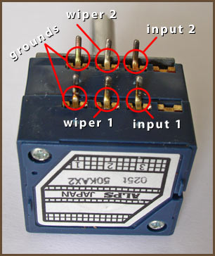
So the easy bit first:
Connect right hot input to input1, left hot input to input 2 on the pot (this is the centre conductor of the RCA input jack)
Connect the wiper 1 (pot output) to pin 2 of the 12AX7
Connect the wiper 2 (pot output) to pin 7 of the 12AX7
Connect the 2 ground pins together and run a wire back to a circuit ground - ideally where the RCA ground connects to.
All should now work ok.
BTW, the part on your photo where you have labelled as the inputs looks a bit weird/hard to see in the photo. Is it some kind of a plate with 2 RCA jacks on it?
Its not too clear from your post whether you realise that the pot goes between the input RCA jacks and the grids of the 2 triodes in the 12AX7.
Here's a pic of the pin arrangement of an alps pot - yours will almost certainly match this:
So the easy bit first:
Connect right hot input to input1, left hot input to input 2 on the pot (this is the centre conductor of the RCA input jack)
Connect the wiper 1 (pot output) to pin 2 of the 12AX7
Connect the wiper 2 (pot output) to pin 7 of the 12AX7
Connect the 2 ground pins together and run a wire back to a circuit ground - ideally where the RCA ground connects to.
All should now work ok.
BTW, the part on your photo where you have labelled as the inputs looks a bit weird/hard to see in the photo. Is it some kind of a plate with 2 RCA jacks on it?
Something else always worth checking - you know those valve pinout diagrams? You realise they are written as if you are looking at the valve upside down. So say, looking at your pic in the first post, take the 12AX7 valve. Start at the gap and working clockwise, you go from pin 1 to 9.
An externally hosted image should be here but it was not working when we last tested it.
Ok...I must be daft because no luck.
Checked pot for resistance and it is OK, but discovered it is actually 500k X 2 (my understanding is that higher resistance rated pots only effect output of higher freq...correct?) so this should be ok to use for my purposes of testing this amplifier.
Connected as per instructions of woodturner-fran and cogsncogs with the exception of C1 in cogsncogs pot schematic (I didn't have one on hand, unfortunately)
Signal Yes. Output Yes...but at max volume distorted (full signal clipping?) or near nil..nothing in between, no matter how I adjust pot.
Replaced first pot with identical value pot, same configuration, also tested for resistance...but same sonic outcome.
Took pot out all together. Connected CD player to installed RCA jack. Signal: Yes. Output: Yes, but maximum full signal distorted to clipping.
Am I missing something!
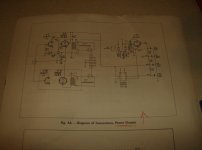
I have included schematic which I found. First one here is original.
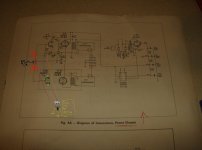
Second schematic has my scribbling on it showing how I wired in my pot.
Comments? Observations?
Are the symptoms a result of high DC content on my signal source as stefkorn suggested earlier?
Pardon my crude renderings and notations on the second schematic on which I clearly reveal my lack of technical sophistication.
Checked pot for resistance and it is OK, but discovered it is actually 500k X 2 (my understanding is that higher resistance rated pots only effect output of higher freq...correct?) so this should be ok to use for my purposes of testing this amplifier.
Connected as per instructions of woodturner-fran and cogsncogs with the exception of C1 in cogsncogs pot schematic (I didn't have one on hand, unfortunately)
Signal Yes. Output Yes...but at max volume distorted (full signal clipping?) or near nil..nothing in between, no matter how I adjust pot.
Replaced first pot with identical value pot, same configuration, also tested for resistance...but same sonic outcome.
Took pot out all together. Connected CD player to installed RCA jack. Signal: Yes. Output: Yes, but maximum full signal distorted to clipping.
Am I missing something!
I have included schematic which I found. First one here is original.
Second schematic has my scribbling on it showing how I wired in my pot.
Comments? Observations?
Are the symptoms a result of high DC content on my signal source as stefkorn suggested earlier?
Pardon my crude renderings and notations on the second schematic
on which I clearly reveal my lack of technical sophistication.Attachments
Last edited:
Looks like you have ground connected at 2 points. Get rid of the light blue connections. Also check that you don't have any kind of short to ground on the input rcas.
By any chance would you have connected that light blue line to the wrong side of the el84 cathode resistor/cap?
Fran
By any chance would you have connected that light blue line to the wrong side of the el84 cathode resistor/cap?
Fran
- Status
- This old topic is closed. If you want to reopen this topic, contact a moderator using the "Report Post" button.
- Home
- Amplifiers
- Tubes / Valves
- Forgive me for I have sinned. Help with Volume Pot!