I have a tube that is a little noisy, the 6c19n it is in a power mu follower configuration with a upper mosfet, it drives mosfets in dc mode and so it haves 2 x 120 volts diff supply.
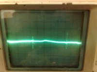
amp works fine, has beautifull sound but it does hiss, I have to put my ears on the speakers to hear it, on the scope it is 0.01 millivolts, the speaker do let it notice me.
I do also see pulses every 10 milliseconds I have the firmanent floating and is dc with lm350 maybe the diff supply is a problem but I need it for dc amp so maybe heater voltage is to high, but so as I did see not and the tube is att negative potential.
The neighbour has installed a wifi transmitter who goes 20 km distance it has a strong transmitter who possible cause this pulses because sometimes she do puls from time to time seeeing the whole supple wobble. if so then I do take staps against him, I don,t like radiation of 5 gigahertz transmitters in my bedroom.
I think this tube is not so quiet.
thanks
Attachments
Last edited:
I have a tube that is a little noisy, the 6c19n it is in a power mu follower configuration with a upper mosfet, it drives mosfets in dc mode and so it haves 2 x 120 volts diff supply.
amp works fine, has beautifull sound but it does hiss, I have to put my ears on the speakers to hear it, on the scope it is 0.01 millivolts, the speaker do let it notice me.
I think this tube is not so quiet.
thanks
I do not think you can hear 10 uV through speaker. But I suggest to measure spectrum of noise before make conclusion about source.
if your amp is an unbalanced input amp, try different grid stop resistor or even the input load resistor from grid to ground. An input impedance mismatch can cause this.
if your amp is a balanced input ( two triodes on bottom, mosfet on top), match grid stop and input load resistors exactly using resistors that have a temp coefficient below 100 ppm.
also try to keep lead length to a minimum running to/from mosfet.
I would rule out the impedance mismatch first before altering the circuit.
thanks for supplying a schematic. you'll have to break the circuit to debug it correctly.
remove negative feeback resistors. a good design guideline: clean up the noise before adding negative feedback so the feedback network have headroom to react to more signal than noise cancellation.
remove impedence mismatch. I would try 220k on the input and driver tube. maybe play with grid stop 1k to 47K. a 100 ohm grid stop resistor means nothing for these tubes in this circuit.
I would temporarily disable the output section to debug the driver stages too. then add the section (divide and conquer methodology)
I have put a complete box on the output, in the tweeter I hear nothing it comes out of the middle tone speaker. also the amp distorts very quicly posseble damage mustage mosfet, gate leaks when measured.

the tekst in schematic about puf puf motorboating is solved, it was high impedance supply of tube driver bad resistors. and the preamp tube in the schematic is not included, it is example of driver and mosfets. it simulates fine.
if mu mosfet dies and speaker is connected then the positieve gate prtection diodes die also, but spares the mosfet output, it is tested.
I will try out your recommends, and disable tthe power stage yes I now, I have already blow up two pairs of mosfets with testing, there gates can sensible for damage so now I have gate protection diodes extra.
thanks for your help. this moment I do listening to it, and like more the my cathode follower version already it sounds so naturally.
Last edited:
if your amp is an unbalanced input amp, try different grid stop resistor or even the input load resistor from grid to ground. An input impedance mismatch can cause this.
if your amp is a balanced input ( two triodes on bottom, mosfet on top), match grid stop and input load resistors exactly using resistors that have a temp coefficient below 100 ppm.
also try to keep lead length to a minimum running to/from mosfet.
I would rule out the impedance mismatch first before altering the circuit.
The noise persist even with removed first stage, it excists in the 6c19n mustage, but straange on scoop I see max 0.0010 volts, normally I have to see that noise, if I remove al the tubes theere is nothing noise anymore, so the power stage is oke, so maybe the digital transmitter of the neighbour give problems with his very strong pulses. I don,t now.
Picture of output 20 volts, it clips negatievely so the mustage mofet is damaged normally a mu stage can output much more, I did indeed measure gate leakage on the mu mosfet making lower impedance for tube..
Attachments

Last edited:
I did find out that D3 and D8 make trouble, just blow them out again when full power test, noise is now very low and only hearable with my ear in the speaker noise is in mid area.
I do now that 2sk1058 has its own gate protection, but I canmt get why these diodes do blow, if the amp is colt no more then 12 volts flow to mosfet gates, and if tubes warm 0 volts afcourse. maybe I have put in diodes like it is in 2sk mosfets. but one thing she did work haha.
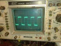
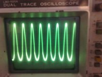
square wave 20 khz without protection diodes the amp did work, some way I do something wrong here, the mustage is strong enough to blow the zeners if amp is full power, maybe because of that the mustage can easely go 100 volts pp and the mosfet power stage max 60 volts, then I can blow the gate protection.
picture is 20 khz square wave on 8 ohms no output coil or correction, some ringing is present but very little, amp is stable even with open input, but the transmittor do radiate in so have do low pass 150 khz.
i thank you all for the help.
I do now that 2sk1058 has its own gate protection, but I canmt get why these diodes do blow, if the amp is colt no more then 12 volts flow to mosfet gates, and if tubes warm 0 volts afcourse. maybe I have put in diodes like it is in 2sk mosfets. but one thing she did work haha.
square wave 20 khz without protection diodes the amp did work, some way I do something wrong here, the mustage is strong enough to blow the zeners if amp is full power, maybe because of that the mustage can easely go 100 volts pp and the mosfet power stage max 60 volts, then I can blow the gate protection.
picture is 20 khz square wave on 8 ohms no output coil or correction, some ringing is present but very little, amp is stable even with open input, but the transmittor do radiate in so have do low pass 150 khz.
i thank you all for the help.
Attachments
Last edited:
Wel after some more tests, it works now, noise is as good as gone, not noticable anymore, diodes D8 who did blow came because of the high output causing diode to clamp and bang, I have put a resistor between mu mosfet and clamp diodes, maybe this way it is much more save.
let me now if you there has ideas further way for improvement, the offset is with the servo 1.50 microvolts, servo is needed with a tube in dc coupled driver.
I have put 470 k grid resistors who did cut the noise and made it more stable.
I still do care for the output mosfets when she again blow in this kind of amplifier, dc coupling with tubes is always more dangereus I think.
this schematic do play now, but with a different input preamp, it is now a srpp with 6sn7 and no feedback..
if it will again blow then I go use a CCS in the driver, then it will be more save .
this driver mustage can drive a headphone easely.
Attachments
Last edited:
I have now listen the whole day to a one channel because I have only one, but the sound is sweet, open, livelike, and not in the speakerbox but in my room, I am pleased with the better sound with a plate follower then a cathode follower special with violins and voices the plate follower wins,
For the feedback haters, in case of a platefollower and current feedback, the amp sounds with feedback a lot better, nice sweet highs, but if I do use voltage feedback then it is a whole differend case, then sound go back in the speakerbox and is very flat, without feedback, the sound gets more freedom.
Still the gate protection is not save i think, I have implement a resistor for current limiting for the mu follower mosfet, further the supply for the tube part and the fet part, I have to give mosfets 2 x 75 volts, and the tube supply 2 x 85 volts, then gate protection diodes will stay in live, now I have 55 volts for the output mosfets and 110 volts for the tube part therefore the mosfets will clipp earlyer then the mustage causing the protection diodes to die.
Am I right here please let me now and if someone nows a better way to protect the mosfets I like it to hear, tips are welcome.
Thank you all for your help, I go make a printed circuit for these.
tomorrow I go change the voltage amp and increase feedback, and listen, feedback is not bad at all if current version not voltage, but I have say this already.
Wel final it works, its stable, and he ringing and overshoot is solved, earth problems are the cause, still it is not yet perfect iin test fase but oke, 20 khz pulses still leak to earth when loaded and 50 watts output and a smoking 20 watt resistor of 8 ohms ;-).
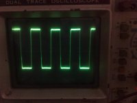
Oke the scope pictures, one with asymetrical clipping, cause? positive protection diodes blown, better then mosfets itselfs..
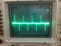
one with pulses leaking from the 20 khz square wave in earth when loaded with a 8 ohm resistor, still present and no solution yet a good pcb and case with solve that, it is 400 mv pp.
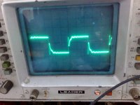
one who get a strange square wave measured on input, when loaded the amp with resistor, this one I can,t get, it leaks trough earth resistance?
sound? very good, best with feedback on (current) so feedback is not always bad special the current feedback ones, it keep amp fast and stay with with bandwith, voltage feedback dont do that.
Last scope picture after reconnect earth, 30 volts 20 Khz in 8 ohms resistor, it did get hot ;-) but nice stable square wave..
Only the first tube give overshoot, it is a srpp with 6h8c so the grid resistor hev to be some higher to tune that.
Oke the scope pictures, one with asymetrical clipping, cause? positive protection diodes blown, better then mosfets itselfs..
one with pulses leaking from the 20 khz square wave in earth when loaded with a 8 ohm resistor, still present and no solution yet a good pcb and case with solve that, it is 400 mv pp.
one who get a strange square wave measured on input, when loaded the amp with resistor, this one I can,t get, it leaks trough earth resistance?
sound? very good, best with feedback on (current) so feedback is not always bad special the current feedback ones, it keep amp fast and stay with with bandwith, voltage feedback dont do that.
Last scope picture after reconnect earth, 30 volts 20 Khz in 8 ohms resistor, it did get hot ;-) but nice stable square wave..
Only the first tube give overshoot, it is a srpp with 6h8c so the grid resistor hev to be some higher to tune that.
Attachments
Last edited:
What is the purpose of the AC virtual ground at D6/D7? It's a ground if voltage exceeds .5 to .7 volts and an open when the voltage is below .5 to .7? I've never seen this done in a signal path (non inverting in this case). Have you checked the reverse voltage leakage across these diodes? could be doing strang things with that inverted input upstream.
the diodes are for protection of the offset servo opamp, it is connected to earth but with a 56 kiloohm resistor from output of amp te sense offset for correction, this opamp however is not yet implemented in the amp.
today I go put a penthode in for test with (current) feedback because the penthode has a mu of 50 in triode mode and the driver a mu of 2.9 thats is 50 x 2.5 = very high (125) so need a little feedback.
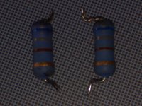
Possible the resistors in picture who are metaloxide can have with 680 ohm has induction, best is bradly here or inductieless metaloxide with tubes it is special important..
Al that typework in english, well over just a while I can type it fully but talking no ;-)
today I go put a penthode in for test with (current) feedback because the penthode has a mu of 50 in triode mode and the driver a mu of 2.9 thats is 50 x 2.5 = very high (125) so need a little feedback.
Possible the resistors in picture who are metaloxide can have with 680 ohm has induction, best is bradly here or inductieless metaloxide with tubes it is special important..
Al that typework in english, well over just a while I can type it fully but talking no ;-)
Attachments
Last edited:
WEk because nobody reacts, I have the news that the amp works and after listing a couple days I am very pleased with the sound, it is very big sound stage, dynamics are huge the speakerbox has a big time hard work with it, it don,t matter where you are everywhere the sound is present, it comes out the speakers.
now it is so far I go build a pcb for it.
here I have made a small film, but don,t take sound that serious with youtube compression.
http://www.youtube.com/watch?v=vVnd-yDKCIk
now it is so far I go build a pcb for it.
here I have made a small film, but don,t take sound that serious with youtube compression.
http://www.youtube.com/watch?v=vVnd-yDKCIk
Last edited:
- Status
- This old topic is closed. If you want to reopen this topic, contact a moderator using the "Report Post" button.
- Home
- Amplifiers
- Tubes / Valves
- noisy tubes