If you can determine that it indeed is 60 Hz or whatever your mains frequency is, and the amp is quiet when the volume control is all the way down; then it's probably a poor circuit ground to chassis ground on your input jack itself. This should be the only connection between the circuit ground and the chassis. Check to see that it's not oxidized and is making a good connection.
I told the poster to parallel twp 20uf new caps if he can't gind a single 40uf new one
Inviato dal mio GT-I5800 usando Tapatalk
Sorry, I was referring to hos post #15 not yours.
Hey everyone
Due to the Easter weekend and the fact that high voltage caps can be a bit tricky to find in SA I havent had a chance to swap out the caps yet. I have a 1000uF 350V Siemens cap from an old professor friend of mine. Could I risk using this cap? The caps in there are obviously much smaller, 20uF each but there are a few in parallel. Should I try that cap or rather wait till I can source the ones with the correct ratings.?
Due to the Easter weekend and the fact that high voltage caps can be a bit tricky to find in SA I havent had a chance to swap out the caps yet. I have a 1000uF 350V Siemens cap from an old professor friend of mine. Could I risk using this cap? The caps in there are obviously much smaller, 20uF each but there are a few in parallel. Should I try that cap or rather wait till I can source the ones with the correct ratings.?
I would use caps as close as possible to the originals if I were you.
+1
At least untill you know what your dealing with extra uF can lift B+ and destroy old components..Coupling caps etc..
")
Regards
M. Gregg
Replacing the original 40uf cap with a 1000uf cap is not a good idea for two more reasons than the reason previously posted by M Gregg and they are: 1 If the old professor's 1,000uf cap hasn't been charged up in several years it may be no good or it may need to have it's plates reformed, either way you will destroy your rectifier if it's a 5U4 or 5Y3 or similar rectifier. The second reason is :Tube rectifiers aren't made to handle such a low reactance load as a 1,000uf cap presents and a 5U4 or 5Y3 will not be long lived if it's connected directly to a 1,000uf cap. Back to your original hunch that it's ground related. Did you say the amp is quiet with the volume all the way down? If so re-read my earlier post.
Hi everyone.
Thanks again for the replies. I am busy trying to remove the old caps but the solder from back then is clearly manlier than solder today. My soldering iron isnt managing to melt them and I am reticent to turn it up to maximum. Will try some plumbers flux to help melt them but any suggestions would be good. Also before starting I tested out some of the voltags and drew a small diagram of the first parts of the Power section. I will post this soon. I ran the amp and confirmed that the hum remains despite any changes in the volume knob. It is also easily as loud as the music.
Thanks again for the replies. I am busy trying to remove the old caps but the solder from back then is clearly manlier than solder today. My soldering iron isnt managing to melt them and I am reticent to turn it up to maximum. Will try some plumbers flux to help melt them but any suggestions would be good. Also before starting I tested out some of the voltags and drew a small diagram of the first parts of the Power section. I will post this soon. I ran the amp and confirmed that the hum remains despite any changes in the volume knob. It is also easily as loud as the music.
Will try some plumbers flux to help melt them but any suggestions would be good.
Wait! Don't do that!
Chris
Hi everyone.
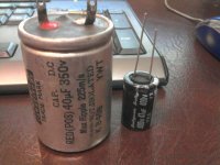
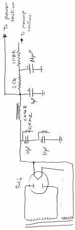
I have the circuit diagram of the PS section attached. I have also attached a pic of the cap that came out of the amp and the cap that is going in. The modern cap is much much smaller than the old one. Is that ok? Has cap technology really moved on that much? Its very impressive. The only thing I will check is that the modern cap has the same max ripple as the what is written on the old cap, namely 225m/a.
It has taken me a while because all the nuts holding the cap clamps are in imperial sizes and I only have metric spanners, had to go buy a shifting spanner to get them out. Thanks again for all the help everyone.
P.S. The flux I have is called self-cleaning flux but I wont use it any more. Why is flux a problem?
Attachments
P.P.S. Forgot to mention. I couldnt get the exact values. 40uF have been replaced with 47uF and the 16uF with 22uF. I hope thats ok. The shop guy also gave me two 33uF he said I could use in series to replace the 16uF. Are those values close enough? Should I use the series 33 or just the 22.
Again thanks a million. Dont know If I would brave this without someone to check with.
Again thanks a million. Dont know If I would brave this without someone to check with.
47uF and 22uF are absolutely fine, they have almost 50% tolerance anyway.
Some fluxes are VERY corrosive. Try to use one specific for electrical work. All fluxes are corrosive - that is how they work.
If you use a resin flux its easy to clean off the residue with a solvent once you have finished soldering.
Some fluxes are VERY corrosive. Try to use one specific for electrical work. All fluxes are corrosive - that is how they work.
If you use a resin flux its easy to clean off the residue with a solvent once you have finished soldering.
Last edited:
You might want to put a resistor in series with the cathode of the rectifier and the new caps.
I'll leave it up to the valvies to recommend what the difference between the new caps and the old caps might mean to the rectifier tube.
For testing I would sub the rectifier tube with SS.
I'll leave it up to the valvies to recommend what the difference between the new caps and the old caps might mean to the rectifier tube.
For testing I would sub the rectifier tube with SS.
- Status
- This old topic is closed. If you want to reopen this topic, contact a moderator using the "Report Post" button.
- Home
- Amplifiers
- Tubes / Valves
- Old amp hum repair